Voyager Series User Manual
SwissMicros GmbH Copyright © 2016–2026 • v1.62 • 2026-07-05
1. Family Members
The Voyager Series of calculators were introduced by Hewlett-Packard in 1981. Each model provided different capabilities and was aimed at different user markets.
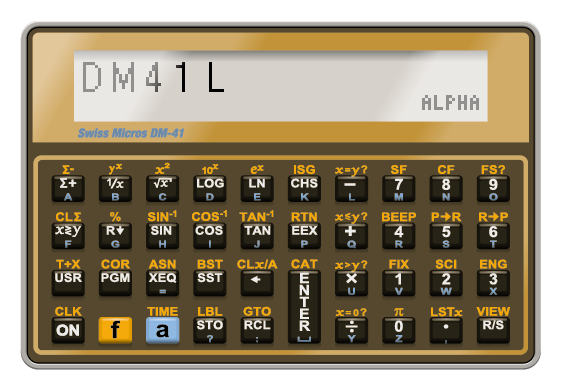
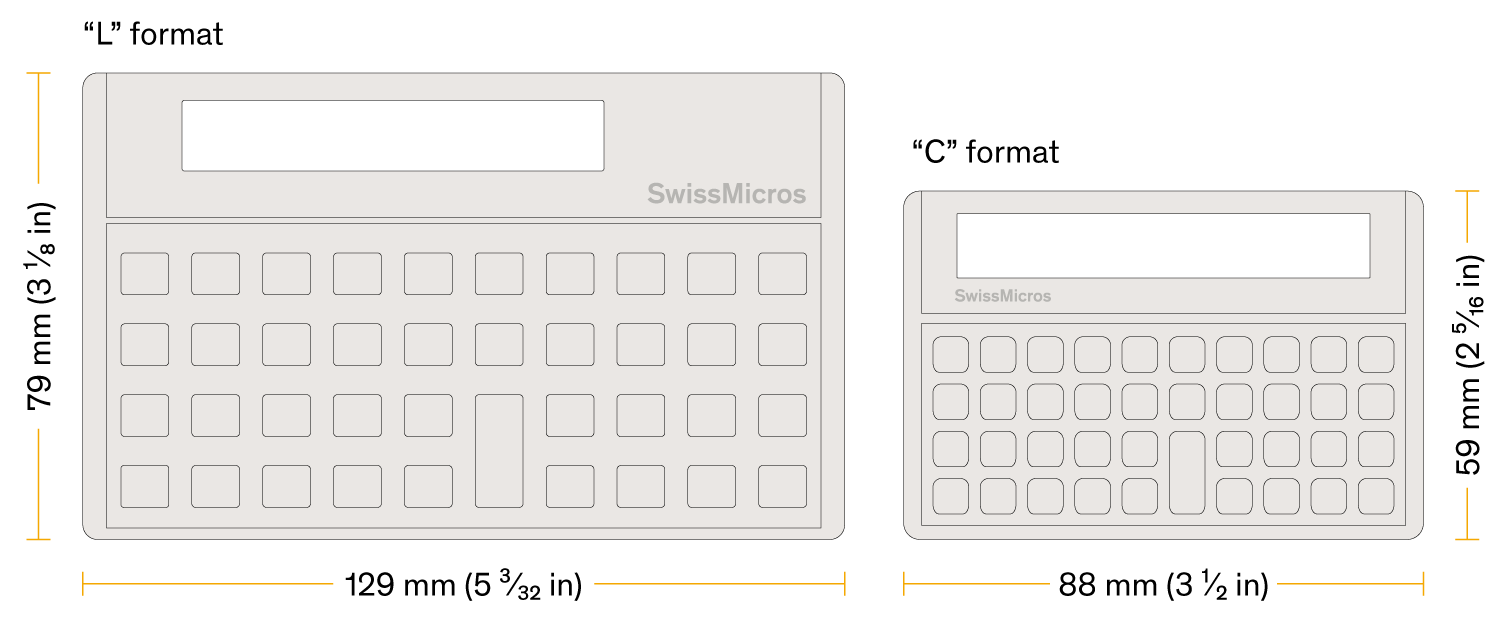
The SwissMicros' Series of the Voyager calculators come in two sizes. See the Illustrations section for a visual size comparison. The credit card sized models (e.g. DM15C) and the original sized models (e.g. DM15L) contain the same electronics and use the same firmware.
In this document, all models are referenced without trailing L or C.
-
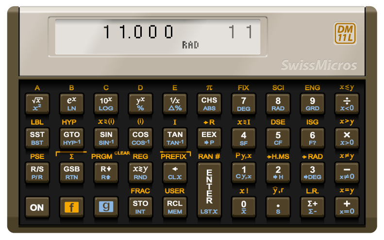
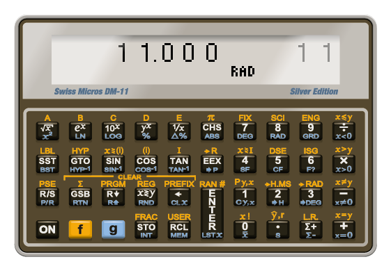
DM11 — mid-range scientific calculator
-
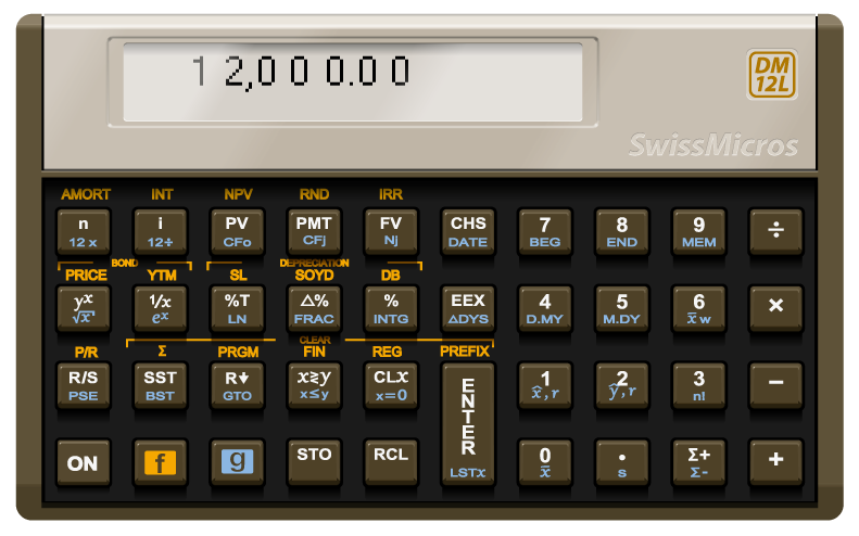
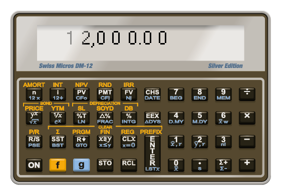
DM12 — business/financial calculator
-
DM15 — advanced scientific calculator
-
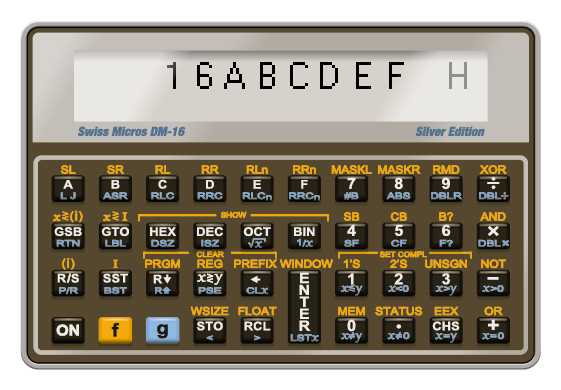
DM16 — computer programmer’s calculator
-
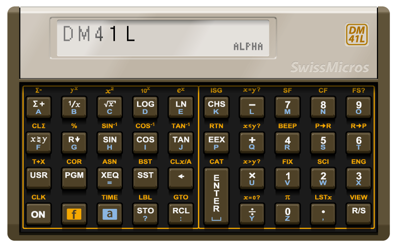
DM41 — a landscape orientated clone of the HP-41CX
2. SwissMicros improvements on the Voyager Series
-
They do not have all the bugs found in the HP-15C LE, see the bug list!
-
They run up to 30 times faster (at 48MHz) than the calculators introduced in the 80s.
-
The USB connection features a command line interface for saving and restoring complete calculator states.
-
Save, edit and restore complete calculator states with one of SwissMicros' online utilities.
-
Firmware update via USB is possible using:
-
the SwissMicros Firmware Update Tool (on Windows) or standard
lpc21isputility on Linux and MacOS, or -
the SwissMicros web-based flashing tool (requires a WebSerial-compatible browser).
-
-
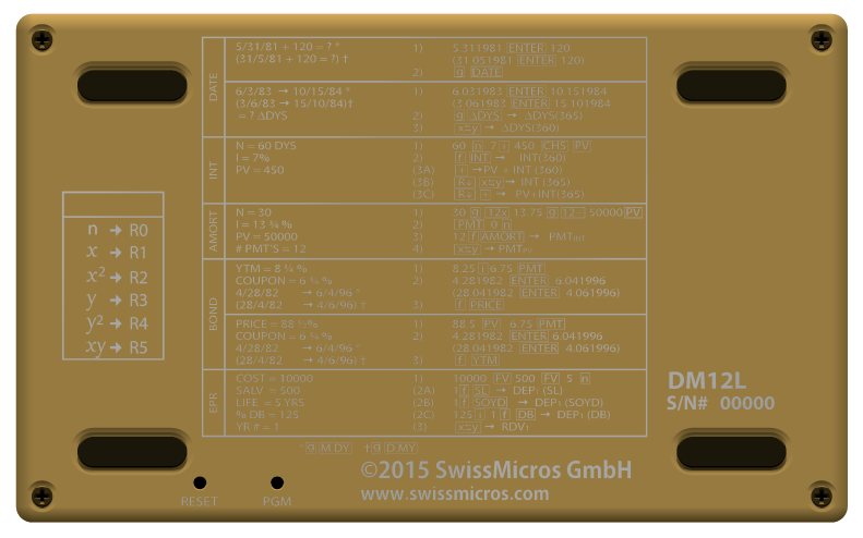
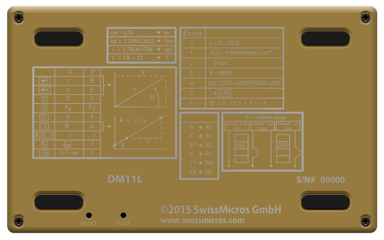
The calculator’s printed circuit board has a reset button located on the back, in the lower left-hand side. The backplate must be removed to access the button.
-
They are still being produced.
2.1. Additions in firmware V33
-
All models get a Setup menu.
-
The DM12, DM15 and DM16 have:
-
a 2-line display mode (showing both the x- and y-registers simultaneously). It is activated by default and can be set to 1-line if so desired;
-
program instructions verbalization (readable function name for each program step);
-
error verbalization (each error code is displayed as readable text);
-
function preview ('a la' HP-41C): holding a key displays the function name, which turns to NULL after about 2 seconds, after which the execution is canceled;
-
pending keys display: when using multi-key instructions on the stack, like STO, the name of the function is displayed until a value key is pressed. Note that an invalid key sequence is denoted by a ~ symbol, for instance STO ~RCL (though only visible while the key is held, as part of function preview described point above).
-
-
The DM15 offers access to constants and execution of conversions.
-
The DM16 has an enhanced SHOW function.
-
There is an optional firmware adding programming steps to the DM16.
3. References and Resources
-
Encode and decode utility (html with jscript) for Save and Restore State function
-
Torsten Manz' excellent HP-15C Simulator supports data exchange with the DM15 under Windows, Linux and Mac OS X
4. Constants and conversions menu (DM15L and DM15C only)
Usage overview:
-
Open the Constants and conversions menu by pressing and then ON.
-
Toggle between Constants and Conversion mode with key x⇆y.
-
Select the desired constant or conversion with the appropriate key.
-
Select the mode of operation with and : either forward (→), backward (←) or push to stack (↑),
-
press ENTER.
| Without user input, the calculator exits the Constants and conversions menu automatically after approximately 55 seconds. |
4.1. Location of constants and conversions on the keypad
In the diagram below, highlighted keys become selectors when the Constants and conversions menu is open.

See the tables below for an exhaustive list of available constants and conversions and their key mapping.
4.1.1. Available constants
| constant | value | unit | 'keypad grid' | key label |
|---|---|---|---|---|
Speed of light |
2.99792458 × 10⁸ |
m/s |
1-1 |
x√y |
Planck constant |
6.62607015 × 10⁻³⁴ |
J s |
1-2 |
ex |
Reduced Planck constant |
1.054571817 × 10⁻³⁴ |
J s |
1-3 |
10x |
Boltzmann constant |
1.380649 × 10⁻²³ |
J/K |
1-4 |
yx |
Avogadro constant |
6.02214076 × 10²³ |
1/mol |
1-5 |
1/x |
Molar gas constant |
8.314462618 |
J/mol/K |
1-6 |
CHS |
Faraday constant |
9.648533212 × 10⁴ |
C/mol |
1-7 |
7 |
Molar volume ideal gas at STP |
2.241396954 × 10⁻⁴ |
m3/mol |
1-8 |
8 |
Atomic mass constant |
1.660539069 × 10⁻²⁷ |
kg |
1-9 |
9 |
Bohr radius |
5.291772105 × 10⁻¹¹ |
m |
1-0 |
÷ |
Gravitational constant |
6.67430 × 10⁻¹¹ |
m3/kg/s2 |
2-1 |
SST |
Acceleration of gravity |
9.80665 |
m/s2 |
2-2 |
GTO |
Elementary charge |
1.602176634 × 10⁻¹⁹ |
C |
2-3 |
SIN |
Vacuum permittivity |
8.854187819 × 10⁻¹² |
F/m |
2-4 |
COS |
Vacuum permeability |
1.256637061 × 10⁻⁶ |
N/A2 |
2-5 |
TAN |
Fine-structure constant |
7.297352564 × 10⁻³ |
2-6 |
EEX |
|
Rydberg constant |
1.097373157 × 10⁷ |
1/m |
2-7 |
4 |
Conductance quantum |
7.748091729 × 10⁻⁵ |
S |
2-8 |
5 |
Magnetic flux quantum |
2.067833848 × 10⁻¹⁵ |
Wb |
2-9 |
6 |
Bohr magneton |
9.274010066 × 10⁻²⁴ |
J/T |
2-0 |
× |
Electron mass |
9.109383714 × 10⁻³¹ |
kg |
3-1 |
R/S |
Neutron mass |
1.674927501 × 10⁻²⁷ |
kg |
3-2 |
GSB |
Proton mass |
1.672621926 × 10⁻²⁷ |
kg |
3-3 |
R↓ |
Astronomical unit |
1.495978707 × 10¹¹ |
m |
3-7 |
1 |
Light-year |
9.460730473 × 10¹⁵ |
m |
3-8 |
2 |
Parsec |
3.085677581 × 10¹⁶ |
m |
3-9 |
3 |
Solar mass |
1.988475 × 1030 |
kg |
3-0 |
– |
Stefan-Boltzmann constant |
5.670374419 × 10⁻⁸ |
W/m2/K4 |
4-4 |
STO |
Wien wavelength constant |
2.897771955 × 10⁻³ |
m K |
4-5 |
RCL |
Jupiter mass |
1.89813 × 1027 |
kg |
4-7 |
0 |
Earth mass |
5.9722 × 1024 |
kg |
4-8 |
• |
Earth mean radius |
6.371 × 10⁶ |
m |
4-9 |
Σ+ |
Moon mass |
7.342 × 10²² |
kg |
4-0 |
+ |
4.1.2. Available conversions
The “conversion” column spells the conversion carried out when in forward mode. To convert the other way around, use backward mode. When in push-to-stack mode, the number in column “value” is used.
| conversion (forward →) | from unit | to unit | op. | value | 'keypad grid' | key label |
|---|---|---|---|---|---|---|
kilometer per hour → mile per hour |
kph |
mph |
÷ |
1.60934 |
1-1 |
x√y |
meter per second → foot per second |
m/s |
ft/s |
× |
3.28084 |
1-2 |
ex |
knot → mile per hour |
knot |
mph |
× |
1.15078 |
1-3 |
10x |
knot → kilometer per hour |
knot |
kph |
× |
1.852 |
1-4 |
yx |
furlong per fortnight → mile per hour |
FpF |
mph |
÷ |
2.688 × 10³ |
1-5 |
1/x |
millimeter → inch |
mm |
in |
÷ |
2.54 × 101 |
1-6 |
CHS |
mile → foot |
mi |
ft |
× |
5.280 × 10³ |
1-7 |
7 |
meter → foot |
m |
ft |
× |
3.28084 |
1-8 |
8 |
kilometer → mile |
km |
mi |
÷ |
1.60934 |
1-9 |
9 |
nautical mile → (statute) mile |
nm |
mi |
× |
1.15078 |
1-0 |
÷ |
kilogram → pound |
kg |
lbs |
× |
2.20462 |
2-1 |
SST |
gram → ounce |
g |
oz |
÷ |
2.83495 × 101 |
2-2 |
GTO |
imperial ton → pound |
ton(imp) |
lbs |
× |
2.240 × 10³ |
2-3 |
SIN |
U.S. ton → pound |
ton(us) |
lbs |
× |
2.000 × 10³ |
2-4 |
COS |
metric ton → pound |
ton(metric) |
lbs |
× |
2.20462 × 10³ |
2-5 |
TAN |
Pascal → pound per square inch |
Pa |
psi |
× |
1.45038 × 10⁻⁴ |
2-6 |
EEX |
Pascal → atmosphere |
Pa |
atm |
× |
9.8692 × 10⁻⁶ |
2-7 |
4 |
Pascal → Torr |
Pa |
torr |
× |
7.50062 × 10⁻³ |
2-8 |
5 |
pound per square inch → Torr |
psi |
torr |
× |
5.17149 × 101 |
2-9 |
6 |
atmosphere → Torr |
atm |
torr |
× |
7.6 × 10² |
2-0 |
× |
Joule → foot-pound |
J |
ft lbs |
× |
7.37562 × 10⁻¹ |
3-1 |
R/S |
kilowatt-hour → foot-pound |
kW h |
ft lbs |
× |
2.655E6 |
3-2 |
GSB |
foot-pound → British Thermal Unit |
ft lbs |
btu |
× |
1.28507 × 10⁻³ |
3-3 |
R↓ |
square centimeter → square inch |
cm2 |
in2 |
÷ |
6.456 |
3-7 |
1 |
square meter → square foot |
m2 |
ft2 |
÷ |
9.2903 × 10⁻² |
3-8 |
2 |
square klilometer → square mile |
km2 |
mi2 |
÷ |
2.58999 |
3-9 |
3 |
acre → square mile |
acre |
mi2 |
× |
1.5625 × 10⁻³ |
3-0 |
– |
degree Celsius → degree Fahrenheit |
°C |
°F |
× |
1.8+32 |
4-4 |
STO |
degree Celsius → Kelvin |
°C |
K |
+ |
273.15 |
4-5 |
RCL |
liter → U.S. gallon |
l |
gal(us) |
÷ |
3.78541 |
4-7 |
0 |
liter → imperial gallon |
l |
gal(imp) |
÷ |
4.54609 |
4-8 |
• |
cubic centimeter → cubic inch |
cm3 |
in3 |
× |
6.10237 × 10⁻² |
4-9 |
Σ+ |
cubic meter → cubic foot |
m3 |
ft3 |
× |
3.53147 × 101 |
4-0 |
+ |
4.2. Modes of operation
Constants and conversions share the same three modes of operation, indicated by an arrow annunciator at the lower right corner of the display. The mode of operation is selected by using keys and and determines what happens when ENTER is pressed.
4.2.1. Constants modes of operation
-
→ : multiply the value in the x-register by the selected constant without losing the t-register.
-
← : divide the value in the x-register by the selected constant without losing the t-register.
-
↑ : push the constant to the x-register.
4.2.2. Conversions modes of operation
-
→ : foward. Convert the dimension in the x-register forward without losing the t-register.
-
← : backward. Convert the dimension in the x-register backward without losing the t-register.
-
↑ : push to stack. The conversion factor is pushed to the x-register.
| Although converting forward often means from Metric to Imperial (just as backward often means from Imperial to Metric), this is obviously not applicable to all conversions. |
4.3. Conversion example
John buys a car in Geneva. His favorite model advertizes a fuel consumption of 7.5l/100km (7.5 liter per 100 kilometer). To better grasp what this means, he needs to convert this to the U.S. standard mpg (miles per gallon). Here’s how:
| keystrokes | stack | description | |
|---|---|---|---|
1. |
0 ENTER ENTER ENTER |
y 0.0000 |
clear the stack |
2. |
100 |
y 0.0000 |
enter 100 kilometers |
3. |
ON |
open the Constants and conversions menu |
|
4. |
( x⇆y ) |
y Conversions |
if necessary, use x⇆y to select Conversions |
5. |
( ) |
if necessary, use to set the mode to forward (annunciator → ) |
|
6. |
9 |
y km → mi |
select the kilometer to mile conversion |
7. |
ENTER |
y 0.0000 |
the value in the x-register is converted to miles |
8. |
7.5 |
y 62.1373 |
enter 7.5 liters; the value of miles is pushed up to the y-register |
9. |
ON 0 |
y l → gal(us) |
open the Constants and conversions menu and select the liter to gallon conversion |
10. |
( ) |
if necessary, use to set the mode to Metric to Imperial (annunciator → ) |
|
11. |
ENTER |
y 62.1373 |
the value in the x-register is converted to gallons, and miles are still in the y-register |
12. |
÷ |
y 0.0000 |
the car gets about 31 miles per gallon |
A representation of the same ratio in metric units, kilometers per liter, can be calculated immediately like this:
| keystrokes | stack | description | |
|---|---|---|---|
1. |
ON 0 |
y l → gal(us) |
open the Constants and conversions menu and select gallon as unit; |
2. |
|
y 1 gal(us) = |
use to set the mode to push to stack (annunciator ↑ ) |
3. |
ENTER |
y 31.3620 |
the amount of liters in a gallon has been pushed to the x-register |
4. |
÷ |
y 0.0000 |
return the amount of miles per liter |
5. |
ON 9 |
y 1 mi = |
open the Constants and conversions menu and select mile as unit; the menu is still in Push to stack mode (annunciator ↑ ) |
6. |
|
y mi → km |
use to set the mode to backward (annunciator ← ) |
7. |
ENTER |
y 0.0000 |
the car gets a mileage of 13.3333 kpl (kilometers per liter) |
5. Enhanced SHOW function (DM16L and DM16C only)
Starting with firmwre V33, the SHOW function (called by pressing and then either HEX, DEC, OCT or BIN):
-
displays all digits of the value in HEX, DEC and OCT modes, which means one no longer has to scroll around to see all the digits;
-
displays up to 20 digits in BIN mode.
6. Battery Replacement
|
SwissMicros Voyager calculators are powered by a standard (non-rechargeable) CR2032 battery. The battery should last many years with normal use. Powering via USB is not supported. |
-
Turn calculator off.
-
Unscrew all back screws (4 screws for the 'L' and older 'credit-card-size' series, 2 screws for the 'C' series).
-
Remove calculator backplate.
-
Replace the battery; calculator data is preserved for about 30 seconds without battery.
-
Put it back together, don’t tighten the screws too much.
| To preserve battery life, without user input the calculator turns off automatically after approximately 3 minutes. |
7. Firmware Update
| It is not possible to break or brick the calculator with any update procedure. |
| All calculator data (i.e. programs, registers, font and stack configuration, etc.) will be lost. Make a backup if needed. |
7.1. Selecting Firmware
7.1.1. Latest Firmware
The latest firmware versions are available at https://technical.swissmicros.com/voyager/firmware/.
Download files using the 'Target save as…' function.
7.1.2. Name Conventions
The basic firmware name consist of two parts
<model>_<version>.hex

Example: DM12_V31.hex
where
- <model>
-
Calculator model. One of
DM11,D12,DM15,DM16,DM41 - <version>
-
Firmware version, e.g.
V33.
Extended firmware name adds name of the extension
<model>_<ext>_<version>.hex

Example: DM15_M80_V31.hex
where <model> and <version> are the same as above and
- <ext>
-
Name of the extension e.g.
M80,M1B
7.1.3. Special DM15 Firmware Versions
There are two special firmware versions for the DM15, version M80 and version M1B.
Both contain the original ROM with modifications to support more memory.
According to the HP-15C Owner’s Handbook, Appendix C: Memory Allocation (pg. 214), the
total allocatable memory is 64 registers and initial Memory Status is 19-46 0-0.
The following table summarizes how this limit is modified in extended DM15 ROMs.
| ROM | Alocatable registers | RAM base addr. | Initial Memory Status |
|---|---|---|---|
DM15 (Original ROM) |
64 |
0xc0 |
|
DM15_M80 |
128 |
0x80 |
|
DM15_M1B |
229 |
0x1b |
|
The default distribution version on DM15 is DM15_M1B with 229 Registers to supply
users with as much memory as possible. Please, keep in mind the original calculator
ROM isn’t designed to handle so much memory and there are known at least two marginal
cases when the calculator can give confusing info or wrong result:
|
Known problems
|
To avoid potential problems, the firmware version DM15_M80 can be used,
where such effects should be less prominent, or even firmware version DM15 with the original ROM code.
7.1.4. Special DM16 Firmware Version
There is a special firmware version for the DM16, version MC0.
It contains the original ROM with modifications to support more memory.
This adds 224 available programming steps, extending the original 203 steps to 427 in total.
7.2. Update using the web-based flashing tool (firmware V33 and above)
-
Go to https://technical.swissmicros.com/voyager/FlashingTool/
-
Connect the calculator to the computer
-
On the web interface, click button Connect; if asked, select correct serial port number
-
Start Bootloader; calculator indicates READY FOR FLASHING
-
On the web interface, click button Select hex-file and point to previously downloaded firmware file
-
On the web interface, click button Program; the flashing procedure starts
-
The calculator automatically resets when flashing is done and the display shows MEMORY CLEAR
7.3. Update on Windows
7.3.1. Required software
-
Download and unpack the SwissMicros Voyage Firmware Tool for updating the calculator
7.3.2. Update
-
Connect the calculator with a miniUSB cable to the computer.
-
Start the Voyage Firmware Tool
-
Press "Open File …" and choose the firmware file
-
Choose "Serial Port", see find Serial Port Number
-
If the calculator is running firmware V33 or above, start Bootloader; calculator indicates READY FOR FLASHING
-
Press the "Program" button in the application
-
If the calculator is running firmware older than V33, press the reset button with a paperclip to initiate the flash process.
If the calculator beeps and displays SERIAL CONSOLE, reset again until the flash process begins. -
The flash progress is displayed in the application and takes about 10-20 seconds depending on the firmware version.
7.4. Update on MacOS
7.4.1. Required Software
-
Ensure the Serial Port driver is installed
-
Download and install MacPort (www.macports.org)
-
Open the Terminal application (Applications→Utilities→Terminal) and run the following commands:
sudo port selfupdate
sudo port upgrade outdated
sudo port install lpc21isp
-
Close the Terminal application
7.4.2. Firmware Update
-
Open the Terminal application (Applications→Utilities→Terminal)
-
Connect the calculator with a miniUSB cable to the computer.
-
If the calculator is running firmware V33 or above, start Bootloader; calculator indicates READY FOR FLASHING
-
Run command:
sudo lpc21isp -control -controlinv -hex <firmware_file> <serial_port> 115200 12000
replace
<firmware_file>with the firmware file name
and<serial_port>with Serial Port Name found in previous stepExample:
sudo lpc21isp -control -controlinv -hex DM15_V31.hex /dev/tty.usbserial-0001 115200 12000
-
If the calculator is running firmware older than V33, press the reset button with a paperclip to initiate the flash process.
If the calculator beeps and displays SERIAL CONSOLE, reset again until the flash process begins. -
Close the Terminal application
7.5. Update on Linux
7.5.1. Required Software
-
Install the
lpc21isptool for firmware update.On Debian based systems run
sudo apt-get install lpc21isp
or run package installer according to the Linux distribution.
7.5.2. Firmware Update
-
If the calculator is running firmware V33 or above, start Bootloader; calculator indicates READY FOR FLASHING
-
Start the flashing utility by
sudo lpc21isp <firmware_file> <serial_port> 115200 12000
replace
<firmware_file>with the appropriate firmware filename and<serial_port>with Serial Port Name found in the previous stepExample:
sudo lpc21isp DM15_V31.hex /dev/ttyUSB0 115200 12000
-
If the calculator is running firmware older than V33, press the reset button with a paperclip to initiate the flash process.
If the calculator beeps and displays SERIAL CONSOLE, reset again until the flash process begins.
7.6. Reset button
The calculator’s printed circuit board has a reset button located on the back, in the lower left-hand side. Depending on the model, the backplate has a hole which allows pressing this button using a paperclip. If this hole is not present, then the button must first be exposed by removeing the backplate. To do this, follow points 1 to 3 from section Battery Replacement.
8. Serial Console
Useful links:
-
Encode and decode utility (html with jscript) for Save and Restore State function
-
A great HP-15C Simulator by Torsten Manz for Windows, Linux and Mac OS X supports data exchange with the DM15.
8.1. Connection to Serial Console
-
Prepare Serial Console program:
8.2. Enable Serial Console Mode
Serial Console Mode is enabled from the Setup menu. Press ON 1-3 ENTER.
| For the meaning of 1-3, see About the 'keypad grid'. |
8.3. Serial Port Drivers
8.3.1. Windows
Download and install Silicon Labs CP2102 USB Driver from Silicon Labs drivers page/Downloads.
|
Windows users should NOT use the "Universal" Windows driver, use the older Windows drivers instead, the newer type has installation issues on Windows 10. |
8.3.2. MacOS
Driver is part of the system since "Big Sur".
For earlier systems download and install the CP2102 Mac OSX driver from Silicon Labs drivers page/Downloads.
8.3.3. Linux
No action needed.
The cp210x driver is part of the kernel build on all major Linux systems.
8.4. Finding Serial Port
8.4.1. Windows
-
Connect the calculator with a miniUSB cable to the computer.
-
Open Device Manager and find the
Silicon Labs CP210xline, -
Note the name given to the USB Serial Port (here :
COM3)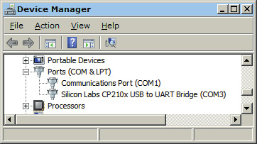
8.4.2. MacOS
-
Ensure the Serial Port driver is installed
-
Connect the calculator with a miniUSB cable to the computer.
-
Find the name of the USB Serial Port
ls /dev/tty.usbserial*
or with Silicon Labs drivers
ls /dev/tty.SLAB*
The port is usually
/dev/tty.usbserial-0001or/dev/tty.SLAB_USBtoUART
If the port isn’t present, check the USB connection to calculator.
8.4.3. Linux
-
Connect the calculator with a miniUSB cable to the computer.
-
In the console run:
dmesg
There should be a message near the end like
cp210x converter now attached to ttyUSB0If so, the full path to the USB Serial Port is
/dev/ttyUSB0
8.5. Console on Windows
8.5.1. Required Software
Setting up a USB Serial Port connection in Windows
-
Download and install PuTTY (http://www.putty.org/)
8.5.2. Connection
-
Connect the calculator with a miniUSB cable to the computer.
-
Enable the Serial Console Mode on the calculator: see Setup menu for more details.
-
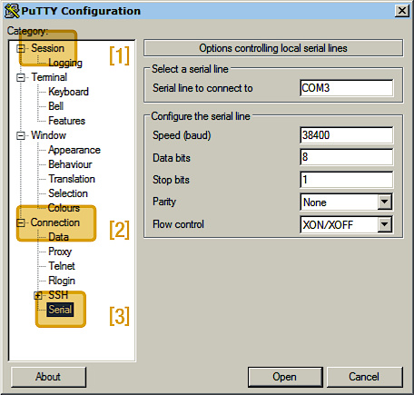
Start PuTTY, go to Session
[1]and select Serial in the panel on the right; go to Connection[2]→ Serial[3]and configure the serial line with the following values:-
Serial line to connect to : Serial Port Name found in previous step
-
Speed : 38400
-
Data bits : 8
-
Stop bits : 1
-
Parity : None
-
Flow control : XON/XOFF (or none)
-
-
Click "Open" to start monitoring Serial Data.
-
The Serial Connection is now established. The monitor window is blank when it starts. Press «?» for help.
-
Pressing any button on the calculator ends the Serial Console Mode.
8.6. Console on MacOS
8.6.1. Required Software
-
Ensure the serial driver is installed.
-
The
screenutility is preinstalled on MacOS system.
8.6.2. Connection
-
Connect the calculator with a miniUSB cable to the computer.
-
Enable the Serial Console Mode on the calculator: see Setup menu for more details.
-
Open the Terminal application (Applications→Utilities→Terminal)
-
Start a console session in terminal application:
screen <serial_port> 38400,8,n,1
replace
<serial_port>with serial port name found in previous stepExample:
screen /dev/tty.usbserial-0001 38400,8,n,1
-
The Serial Connection is now established. The monitor window is blank when it starts. Press «?» for help.
-
Pressing any button on the calculator ends the Serial Console Mode.
-
End the console session: press CONTROL + a then k then y
-
Disconnect the calculator
-
Close the Terminal application
8.7. Console on Linux
8.7.1. Required Software
-
Install the
putty.On Debian based systems run
sudo apt-get install putty
or run package installer according to the Linux distribution.
8.7.2. Connection
-
Connect the calculator with a miniUSB cable to the computer.
-
Start PuTTY
-
go to "Session" and select Serial in the panel on the right
-
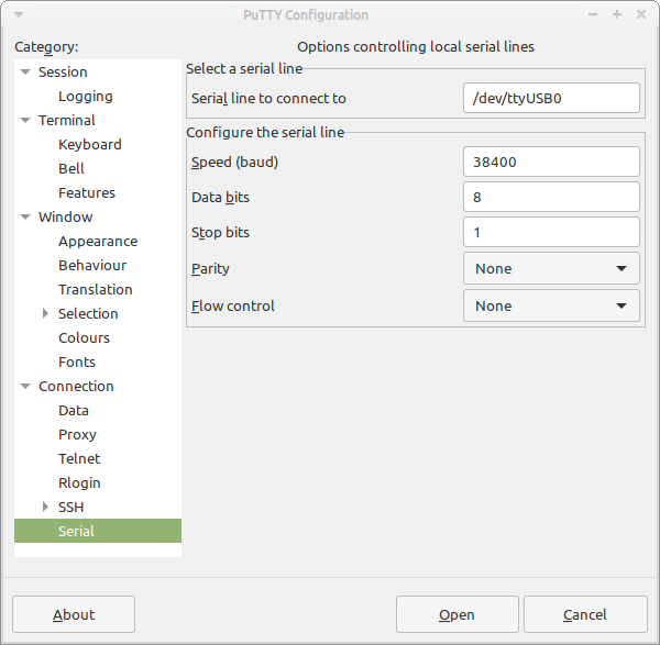
go to Connection → Serial and configure the serial line using the following values. The rest should be left to default (check image below):
-
Serial line to connect to: use Serial Port Name found in the previous step
-
Speed : 38400
-
No flow control
-
-
Enable the Serial Console Mode on the calculator: see Setup menu for more details.
-
Click "Open" to start monitoring Serial Data.
-
The Serial Connection is now established. The monitor window is blank when it starts. Press «?» for help.
-
Pressing any button on the calculator ends the Serial Console Mode.
9. Commands in Serial Console
Once the serial connection to the calculator is established, calculator responds to switching to Serial Console Mode with text:
<model> ready
where <model> is calculator model, e.g. for DM15_M80 it writes to the serial console
DM15_M80 ready
This also indicates that the serial console is ready to accept commands.
As a response to ENTER in serial console window the calculator responds with
command prompt, which is
DM41>> - for DM41 model, or
VOYAGER >> - for other models
A command prompt is also displayed whenever the calculator finishes a command and is ready for the next one.
If an invalid command is entered or ? command is used, the calculator responds
with firmware version and list of available commands, e.g. for DM15_M80_V31:
VOYAGER >> ?
Firmware DM15_M80_V32

?          Help
p          Key press
s          Dump memory
l          Load memory
ct         Console timeout
bootloader Invoke Bootloader
t          Get time
ts         Set time
td         Update time
kb         Toggle keyboard output to console
d          Toggle display output to console
b          Read battery voltage

Type '<command> ?' for params
VOYAGER >>
Next chapters describe several important commands in more details.
9.1. Save and Restore State
Here state refers to the complete contents of the calculator, i.e. stack, registers, programs, etc.
| Calculator setup items like date/time, font selection, stack format (1- or 2-line), annunciator position, dot/comma separator, LCD contrast, and CPU speed are not part of the state. |
9.1.1. Saving calculator memory
-
Establish a connection to the Serial Console
-
To dump contents of calculator memory, enter:
s -
The memory dump is displayed followed by command prompt
-
This dump can be copied, pasted and saved to a text file (including the short line at the top which describes the calculator model) to be later restored to the calculator
9.1.2. Restoring calculator memory
-
Establish a connection to the Serial Console
-
Engage calculator Restore Mode by entering:
l(lowercase «L») -
The command prompt changes to:
Waiting for data… -
Copy all characters from the memory dump, including the short line at the top which describes the calculator model
-
Paste it in the monitor window
-
Monitor window outputs:
Read OK
and the command prompt is displayed -
Calculator memory is now restored
9.2. Set time and date
9.2.1. Getting calculator internal date and time
-
Establish a connection to the Serial Console
-
In the serial monitor window, enter:
t -
The monitor window returns date, time and day of the week in format:
YYYY-MM-DD HH:MM:SS DDD
9.2.2. Setting date and time
-
Establish a connection to the Serial Console
-
The command to set date and time is
ts <YYYYMMDD> <HHMMSS>for instance for September 22nd of 2016, 6:30 PM, enter the following command:
ts 20160922 183000 -
Now, date and time are set
10. Setup menu
To enter the menu
-
on the DM41, press and then (to execute function TIME, simply press again),
-
on all other calculators, press and then ON.
From there, the various items of the menu can be selected by pressing the appropriate menu keys. Each item of the menu allows to adjust certain settings (like Adjust date/time or LCD Contrast) or execute a special function (like Display time/date or Switch to serial console). Press ENTER to enter the adjustment screen or execute the function.
| On firmware older than V33, setup items are accessed by using Special Key Combinations (which remain available from firmware V33 onwards). |
| Without user input, the calculator exits the Setup menu automatically after approximately 55 seconds. |
See the table below for an exhaustive map of available Setup menu items and their corresponding grid location and key label, for each Voyager calculator model. (The 'keypad grid' column shows the coordinates of the key, please see About the 'keypad grid'.)
| Setup menu item | 'keypad grid' | DM11 key | DM12 key | DM15 key | DM16 key | DM41 key |
|---|---|---|---|---|---|---|
1-1 |
√x |
n |
√x |
A |
Σ+ |
|
1-2 |
ex |
i |
ex |
N/A |
N/A |
|
1-3 |
10x |
PV |
10x |
C |
√x |
|
Start bootloader |
1-4 |
yx |
PMT |
yx |
D |
LOG |
1-5 |
1/x |
FV |
1/x |
E |
LN |
|
1-6 |
CHS |
CHS |
CHS |
F |
CHS |
|
2-6 |
EEX |
EEX |
EEX |
BIN |
EEX |
|
4-4 |
STO |
STO |
STO |
STO |
STO |
|
4-5 |
RCL |
RCL |
RCL |
RCL |
RCL |
|
1-7 |
7 |
7 |
7 |
7 |
N/A |
|
3-7 |
1 |
1 |
1 |
1 |
N/A |
|
3-8 |
2 |
2 |
2 |
2 |
N/A |
|
1-9 |
9 |
9 |
9 |
9 |
8 |
|
Keyboard test |
1-0 |
÷ |
÷ |
÷ |
÷ |
9 |
Self test |
2-0 |
⨯ |
⨯ |
⨯ |
⨯ |
N/A |
Power reset |
3-0 |
− |
− |
− |
− |
N/A |
Endless test |
4-0 |
+ |
+ |
+ |
+ |
N/A |
4-8 |
. |
. |
. |
. |
N/A |
|
2-1 |
SST |
yx |
SST |
GSB |
x≶y |
|
2-2 |
GTO |
1/x |
GTO |
GTO |
N/A |
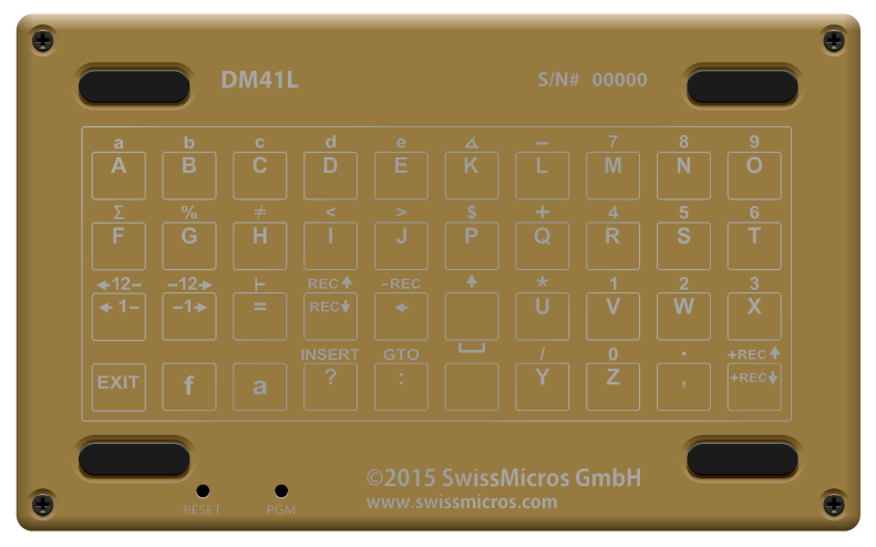
10.1. About the 'keypad grid'
There are two ways to reference a key:
-
by its label, which sometimes changes from model to model in the Voyager series,
-
by its location in the 'keypad grid', which is agnostic to the calulator model.
A Setup menu item, when available, has the same location on the 'keypad grid', across all Voyager models. For instance, the Serial console item is on key 1-3 on all supported models, where 1 is the first row, and 3 the third column. The 'keypad grid' has rows numbered 1 to 4 and columns numbered 1 to 0.

10.2. Display date/time
Invocation: Setup menu + 1-1.
Date and time are displayed on the LCD for 5 minutes. Press any key to cancel.
10.3. Benchmark
Invocation: Setup menu + 1-2.
Evaluate speed compared to original calculator and return factor to x-register.
10.4. Start bootloader
Invocation: Setup menu + 1-4.
The bootloader is a fixed part of the CPU firmware which allows to flash new firmware. This function puts the calculator CPU in a state where it is able to accept a firmware update over serial link.
| To cancel Bootloader, the physical reset button on the calculator PCB must be pressed. |
10.5. System info
Invocation: Setup menu + 1-5.
Displays firmware version, battery voltage, current frequency, and a copyright notice.
10.6. LCD Contrast
Invocation: Setup menu + 1-6.
This menu item starts LCD contrast configuration.
LCD contrast configuration consists of two parameters:
-
parameter 1: LCD brightness,
-
parameter 2: LCD voltage.
Usage:
-
parameter 1: up 4-0, down 3-0,
-
parameter 2: up 4-9, down 3-9.
The LCD configuration:
-
is automatically left without any change after 10 seconds of inactivity,
-
can be left without configuration change at any time by ON key,
-
can be confirmed and saved by ENTER key.
10.7. LCD Contrast Reset
Invocation: Setup menu + 2-6.
Resets the LCD contrast configuration to the default values.
10.8. RTC -1 hour
Invocation: Setup menu + 4-4.
Decrements the real-time clock by one hour, useful for adjusting to daylight saving time.
10.9. RTC +1 hour
Invocation: Setup menu + 4-5.
Increments the real-time clock by one hour, useful for adjusting to daylight saving time.
10.10. Cycle fonts
Invocation: Setup menu + 1-7.
The models DM11, DM12, DM15 and DM16 include several font types. This function cycles through them.
| There are only 2 fonts available in 2-line display. |
10.11. 1-line display
Invocation: Setup menu + 3-7.
Sets the display to 1-line mode (only the x-register is visible).
10.12. 2-line display
Invocation: Setup menu + 3-8.
Sets the display to 2-line mode (the x-register and y-register are both visible).
| In this mode, only 2 fonts are available. |
10.13. Toggle CPU speed
Invocation: Setup menu + 1-9.
The calculator supports two CPU speeds:
-
Normal - CPU runs at 12MHz
-
Fast - CPU runs at 48MHz
This function cycles through them.
10.14. Toggle dot/comma
Invocation: Setup menu + 4-8.
Toggles between two modes: dot as decimal separator and comma for digit grouping, and vice-versa.
10.15. Adjust date/time
Invocation: Setup menu + 2-1.
The date and time are displayed in YYYY-MM-DD and 24-hour format. The currently selected parameter blinks.
Usage:
-
to increase or decrease currently selected parameter, use + and −, respectively;
-
to select the next or previous parameter, use ⨯ and ÷, respectively.
The settings are changed immediately. Press ON or ENTER to exit.
10.16. Annunciator Location
Invocation: Setup menu + 2-2.
This function toggles between location for the annunciators of the Voyager Series (except the DM41), displayed either below the digits (default) or above the digits.
| In 2-line display mode, annunciator location is fixed and unffected by this setting. |
11. Special Key Combinations
Items from Setup menu are available without entering the menu, by using simultaneous keypresses, like so:
-
Turn off calculator,
-
press and hold the desired menu key listed above,
-
press and release ON,
-
release first button pressed.
| Setup menu is only available starting with firmware V33 (the currently installed firmware can be confirmed by displaying the System info screen). The DM41 does not have the Setup menu feature, and thus Special Key Combinations is the only way to access setup items. |
Appendix A: SDK
SwissMicros believes that the user should have full control over the hardware. SwissMicros provides an SDK to get developers started.
The Voyager Series SDK can be downloaded from: dm_lpc111x_sdk.tar.gz.
Appendix B: Matrices in Extended DM15
The hp15c was a highlight of its time. It is noteworthy that the original nut code of hp15c is apparently fit for an extension of its RAM. As far as I can say, it work best for all but the inverse of a matrix larger than 8x8. The largest matrix the original hp15c could store was 8x8 - so the algorithm was optimized for that maximum in size.
The reason why the original algorithm fail for larger matrices is that it has to reorder the rows of the matrix under certain circumstances. How the rows are reordered is stored in the signs of the diagonal elements of the matrix. In a register (7 bytes - 14 nibbles) the sign is stored in a nibble as 0 for + or 9 for -. A nibble hold 4 bits - so in the sign is place for additional 3 bits. These remaining 3 bits are used to store the original row offset. This only work up to 8 rows. If a matrix has more than 8 rows, this will not work anymore. :-(
The intermediate step used for matrix division, matrix inverse and determinant of a matrix is called LU decomposition. It is described in the "HP15C advanced functions handbook" - Section 4 - "Using Matrix Operations" - "Understanding the LU Decomposition" on page 96/97 of the original manual from 1982 or on page 82/83 of the reproduction from 2012.
Do not trust the results of matrix division, matrix inverse or determinant of a matrice larger than 8x8.
An easy counter-example:
A(i,j) = 0 if j < (n - i + 1);
Otherwise A(i,j) = 1

b(i) = i
1 <= i,j <= n

A*x = b

=>

x(i) == 1 for all 1 <= i <= n

 ----
A * x = b

0 0 0 0 ... 0 1 x(1) = 1
0 0 0 0 ... 1 1 x(2) = 2
...
0 1 1 1 ... 1 1 x(n-1) = n-1
1 1 1 1 ... 1 1 x(n) = n
The following program, also available as a dump, will fill pre-dimensioned matrix A, set size of b, fill b and set result matrix to C.
* f LBL D                001-42,21,14
  RCL DIM A              002-45,23,11
  STO 2                  003-   44  2
  g TEST 6  x≠y?         004-43,30, 6
  g RTN                  005-   43 32
  f MATRIX 1  R0,R1 := 0 006-42,16, 1
* f LBL 0                007-42,21, 0
  RCL 2                  008-   45  2
  RCL 0                  009-   45  0
  -                      010-      30
  1                      011-       1
  +                      012-      40
  RCL 1                  013-   45  1
  g TEST 8  x<y?         014-43,30, 8
  g CLx                  015-   43 45
  g TEST 1  x>0?         016-43,30, 1
  1                      017-       1
  USER STO A / USER      018u   44 11
  GTO 0                  019-   22  0
  RCL 2                  020-   45  2
  1                      021-       1
  f DIM B                022-42,23,12
  f MATRIX 1  R0,R1 := 0 023-42,16, 1
* f LBL 1                024-42,21, 1
  RCL 0                  025-   45  0
  USER STO B / USER      026u   44 12
  GTO 1                  027-   22  1
  f RESULT C             028-42,26,13
  g RTN                  029-   43 32
DM15_M1B
00  00000000000000  00000000000000  00000000000000  00b10000000000
04  000000fffff000  0000000000000c  00000000000008  c0b9ab9a000eae
08  00000000000000  2fafcbefbe2280  00000000000040  00000000000000
10  00000000000000  00000000000000  00000000000000  1a000000000000
14  01017980433000  1b2d2d2d2d2d2d  000000000005fb  00000000000000
18  00000000000000  0000000000007f  00000000c00000  00000000000000
bc  00000000000000  01000000000001  00000000000000  00000000000000
f8  00000000000000  00000000000000  00000000000000  0000b28c114bbf
fc  300191ff9bf132  104abff171a278  31faf1fb303200  91ffb27642aa0d
A: 000000fffff000  B: 000000fffffeae  C: c0b9ab9a000eae
M: f000bffffff7fb  N: 00000000000000  G: 04
Then use it like this:
<n> ENTER f DIM A
f D
RCL MATRIX b
RCL MATRIX A
/
f USER
f MATRIX 1
RCL C
RCL C
...
f USER
To do the test:
-
Dimension A
-
Call D
-
Key in the calculation
-
Divide b by A
-
Check if all elements of C are equal to 1
If 0<n<9 all elements of C will be equal to 1, but if n>8 the algorithm will fail and C will hold totally wrong values. Due to an overflow, the display will blink.
Further investigations lead to the following results:
-
Mx 1x1 .. 8x8 give correct results.
-
Mx 9x9 .. 11x11 give wrong results.
-
Mx 12x12 .. 14x14 never end ⇒ endless loop
Appendix C: Specifications
C.1. Hardware
| Specification | Details |
|---|---|
Construction |
Case made from sandblasted titanium, laser engraved |
Software |
ARM microcontroller emulating the NUT processor |
Processor |
LPC1115 32-bit ARM Cortex-M0 microcontroller |
Memory |
64 kB internal flash, 8kB RAM |
Display type |
Reflective Positive FSTN |
Display resolution |
132 × 16 pixels |
Display active area |
69 × 10 mm |
Display dot pitch |
524 × 626 µm |
Connectivity wired |
USB-C port for firmware update and data exchange via CDC |
Battery type |
1 × CR2032 lithium coin cell, 3.0 volts[1] |
Battery life |
Up to 5 years |
Sound |
4 kHz resonance frequency Piezo-electric buzzer |
Size |
88 × 58 × 9 mm |
Weight |
62 g |
Warranty |
5 years |
| [1] The battery isn’t rechargeable. See Battery Replacement. |
The screws used to secure the calculator backplate are titanium Philips countersunk M2.5×4mm.
C.2. Illustrations
C.2.1. Horizontal unit size comparison
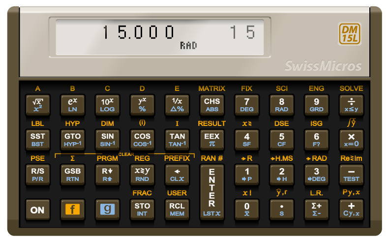
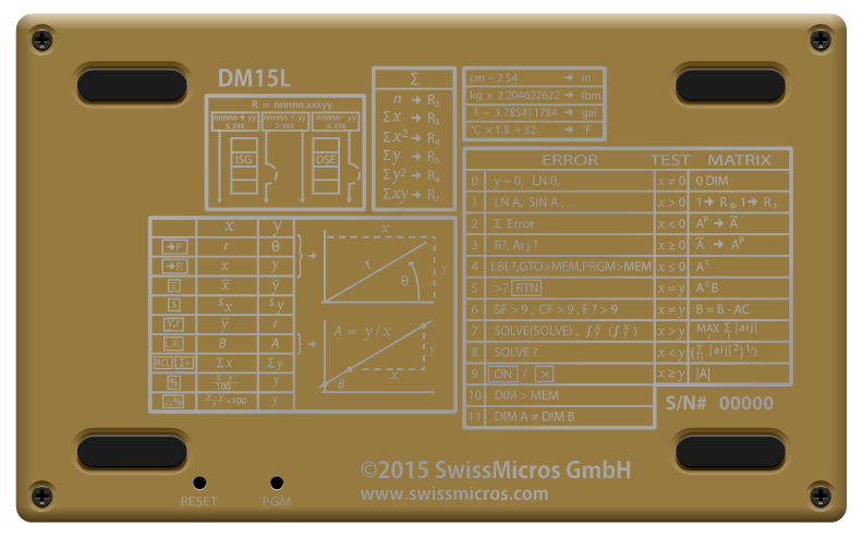
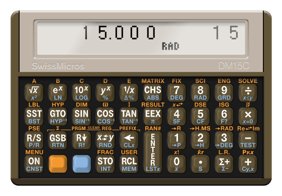
C.2.2. DM15
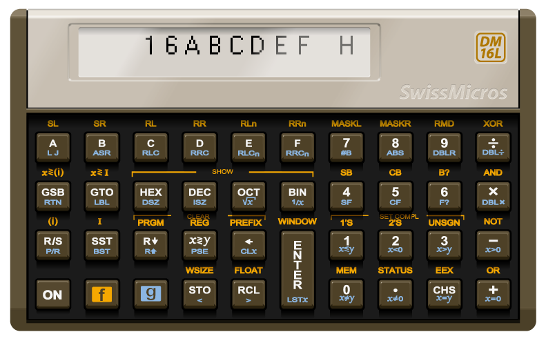
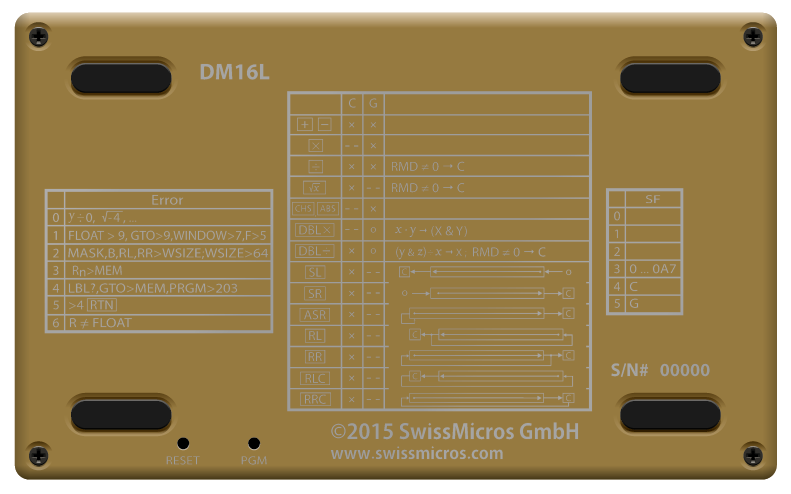
C.2.3. DM16
C.2.4. DM12
C.2.5. DM11
C.2.6. DM41