DM41X User Manual
SwissMicros GmbH Copyright © 2016 – 2025 v1.33 2025-10-01
1. About this User Manual
This user manual refers to special features of DM41X. PDF version of this manual is available at https://technical.swissmicros.com/dm41x/doc/dm41x_user_manual.pdf.
Search internet for documentation of original HP-41C calculator and related modules and utilities. Especially useful is HP41.org site, where manuals could be viewed on-line and/or downloaded complete DVD for off-line access.
Other sites with manuals:
Many thanks to Robert Prosperi and Ángel M Martin for contributions to DM41X project and this manual.
2. General Information
The DM41X comes with
-
41CX system ROMs (with several patches)
-
Full "Extended Memory" configuration - i.e the basic 41CX extended memory + two additional extended memory modules
-
Possibility to load other 41C modules from
.modfiles -
IR printing support
-
Internal FAT disk for modules, programs and configuration backups
-
Possibility of keyboard overlays
2.1. Specifications
| Specification | Details |
|---|---|
Construction |
Case made from stainless steel, matte black Physical Vapour Deposition (PVD) coated and laser engraved |
Software |
Based on the legendary HP-41CX, it runs on the SwissMicros Operating System (DMCP). Logical compatibility with existing HP expansion modules. |
Processor |
Ultra low power ARM Cortex-M4F 80 MHz |
Flash memory |
64 MBit external flash |
Display type |
Monochromatic ultra high contrast (14:1) transflective memory LCD display |
Display resolution |
400 × 240 pixels |
Display active area |
58.8 × 35.28 mm |
Display dot pitch |
147 × 147 µm |
Connectivity (PC) |
USB-Micro-B port, connects as USB mass storage device |
Connectivity (IR) |
IR Transmitter compatible with the original HP-82240A/B printer |
Battery type |
1 × CR2032 lithium coin cell, 3.0 volts[1] |
Battery life |
Up to 3 years |
Sound |
4 kHz resonance frequency Piezo-electric buzzer |
Size |
77 × 144 × 12 mm |
Weight |
180 g |
Warranty |
5 years |
| [1] The battery isn’t rechargeable. See Battery chapter below for battery replacement and further info. |
The screws used to secure the calculator backplate are black zinc plated Philips countersunk M2.5×6mm.
2.2. CPU Speed
CPU speed is 24MHz when running on battery (due to limited battery current) and increases to 80MHz when the USB cable is connected.
2.3. IR Printing
The DM41X Calculator includes IR output and can print on an HP 82240A/B infrared printer using 2 different HP modules, in this manual called "Thermal Printer" and "IR Printer" respectively:
-
Thermal Printer
This printer module, available since the initial release of DM41X, simulates printing to an HP-82143A (wired) printer for the HP-41, and its functions and behavior are the same as implemented in the wired 82143A printer; see that Owner’s Handbook for details about usage, behavior, print modes, flags, etc. (https://literature.hpcalc.org/items/400).
The original 82143A had hardware buttons to control various modes; controlling these modes when using the Thermal Printer module follows the conventions found in the HP-82160A HP-IL Interface (https://literature.hpcalc.org/items/422), see section 2. -
IR Printer
This printer module, available starting with release 2.2 of the DM41X, simulates printing using an HP-82242A "Blinky" IR module; see that Owner’s Manual for details about usage, behavior, flags, etc. (https://literature.hpcalc.org/items/490).
Note that either module has to be plugged-in first. See Plug-in Printer Module for more information.
2.4. Internal FAT disk
The calculator has 6MB of internal flash storage formatted as a FAT filesystem that is used for loading/saving programs and for backing up calculator state. It is accessible as USB disk when activated via the menu .
|
Internal flash has limited amount of write cycles. While the lifetime with ordinary usage could be dozens of years, an excessive number of writes will wear the flash memory much quicker. The datasheet mentions a minimum of 100,000 write cycles, which sounds like a lot, but any change in the filesystem means overwriting at least part of the file allocation table, which is stored in a static location. In an attempt to wear out/kill the onboard flash memory chip, a 72-day test of continuous operation was setup. The test had to be interrupted for unrelated reasons, but when stopped, the near million (995'341) write cycles had not been enough to kill the chip. The only sign of wear was a 20% increase in erase/write cycle time. Despite these numbers, we are confident there is still a possibility for the flash memory to fail before the rest of your rugged calculator, under certain categories of heavy use at least. Should this happen, you would have to replace the flash chip, which is a relatively inexpensive part. If needed, SwissMicros will replace the chip at no cost, but shipping costs must be covered by the customer. |
Calculator comes with pre-filled FAT disk contents. In case the contents of the FAT area is lost it could be always downloaded from the SwissMicros DM41X FAT files page. There are the contents of individual directories accessible separately or the whole contents of FAT disk can be downloaded as single zip file DM41X.zip.
There are several directories with special names (and purpose) on the FAT disk:
- /BACKUP
-
Contains backup files written by complete calculator backup
- /HELP
-
Contains help file(s) for built-in DM41X help that can be activated from CST menu.
- /KEYS
-
Contains files with Custom Menu key mappings.
- /MODS
-
Default directory for module files.
- /OFFIMG
-
Bitmap files from this directory are displayed when the calculator is turned off. See OFF Images chapter for more details.
- /PROG
-
Raw files with programs are loaded/saved from/to this directory.
- /RAM
-
Contains saved RAM pages see section RAM pages for more details.
- /SCREENS
-
Screenshots of calculator LCD are saved into this directory. See LCD Screenshots for more details.
- /STATE
-
Calculator state files with extension
.d41are stored in this directory. See Load State or Save State how the load or save calculator state.
2.5. Keyboard Overlays
Extruded rim of the DM41X allows the use of keyboard overlays.
Template for the keyboard overlay with dimensions can be found at http://technical.swissmicros.com/graphics/key_overlay_DM42.PDF
2.6. Battery
The calculator uses a single CR-2032 Lithium 3V battery. It is not rechargeable, therefore it has to be replaced when depleted.
| Please remember it is always wise to make calculator data backup before battery replacement. Use USB power during data backup if possible. |
You can power calculator from USB during battery replacement.
To change the battery:
-
remove the 2 screws on the upper rear of the case,
-
remove the back,
-
(optional) connect USB cable to prevent power loss
-
extract the old battery by gently pushing it out of the holder from the bottom towards the top of the case;
-
then insert the new battery with plus (+) side facing up (away from the board),
-
slide all the way down to the bottom of the holder,
-
then replace the back and screw-in the 2 original screws.
3. Calculator Extensions
3.1. Large LCD Screen
3.1.1. Calculator Mode - Stack
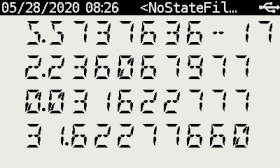
Stack view displays all stack registers with X at the bottom:
T
Z
Y
X
Note that while the emulation is running (e.g. a program is executing) only the portion of the screen corresponding to calculator LCD is updated. All other portions of the screen are updated when emulation stops (e.g. if program stops or waits for user input).
3.1.2. Calculator Mode - SI
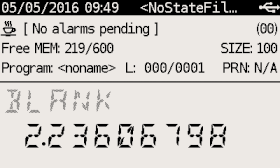
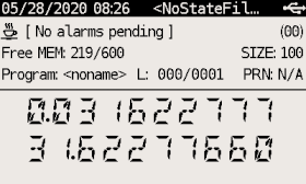
System Info View comes in two variants:
- SI_XA view
-
Displays X and Alpha registers along System Info.
- SI_XY view
-
Displays X and Y registers along System Info.
Note that while the emulation is running (e.g. a program is executing) only the portion of the screen corresponding to calculator LCD is updated. All other portions of the screen are updated when emulation stops (e.g. if program stops or waits for user input).
The upper portion of the screen contains useful details about your 41X status and configuration.
The 1st line displays status of your Alarms.
There are 3 icons on the far left:
-
A coffee cup indicates that no alarms are pending
-
An alarm clock means you have at least one pending alarm
-
A bell means you have a past-due alarm
Next, the alarm text of your next pending (or past-due) alarm is shown.
On the far right, the number of pending alarms is shown in parentheses.
The 2nd line displays your memory status.
On the far left, free (available for use) main Program Memory and free Extended Memory are shown as xxx/yyy.
On the far right on line 2 is the current 41 SIZE status, indicating how many data storage registers have been allocated.
The 3rd line displays information about your current Program and Printer status.
Starting from the left, the program’s name (topmost global Alpha label), current line number and max number of lines is displayed.
On the far right of line-3, the current printer status is displayed following the PRN: label as follows:
| MAN |
Manual Print Mode |
| TRA |
Trace Print Mode |
| NRM |
Normal Print Mode |
| OFF |
The Printer has been disabled (via CF 21 – note, this is reset to ON following each turn-on) |
| N/A |
The Printer Module has not been plugged-in (see section 4.2) |
See the HP-82160A HP-IL Module manual section ‘Flags and the Printer’ on pp. 9-10 for use and meaning of the various Printer modes and controls described above, activated using Flags 15, 16 and 21. All modes described there are supported except for the ‘TRACE with stack’ option. Other print modes (e.g. Double-wide and Lower-case) are controlled using the other flags described in this section. All of these print modes apply to both the "Thermal Printer" and "IR printer" (HP 82242A "Blinky") modules.
| If you have a printer module installed, and no thermal printer is being used, program execution will not halt when encountering a VIEW or AVIEW instruction. See the HP-82160A HP-IL Module manual section ‘Printing During Program Execution’ on pp. 28-29 for details about how to control your desired behavior. You may of course also simply Unplug the printer module to have default (expected) behavior when not using a printer. |
3.1.3. Program Mode
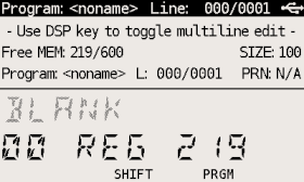
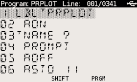
Note that while the emulation is running (e.g. catalog list is executing) only the portion of the screen corresponding to calculator LCD is updated. All other portions of the screen are updated when emulation stops and editing of current program line is finished.
3.2. Special Keys
DM41X has several additional keys not present on original 41C models. Following list summarizes all the additions:
- ‣ CST - Custom Menu key
-
Activates Custom Menu
- ‣ SHIFT CST - CONF
-
Activates Custom Menu configuration screen
- ‣ DSP - Change display key
-
Cycles view modes:
- Calculation mode
- Programming mode
-
-
SI PRGM view - single line basic PRGM view
-
Multiline PRGM view - 4 lines
-
Multiline PRGM view - 6 lines
-
Multiline PRGM view - 8 lines
-
- ‣ SHIFT DSP - PRN
-
The same as pressing "PRINT" button on original 82143A thermal printer. See IR Printing for more details. Note that it directly invokes PRX when "IR printer" is used (same as with "Thermal printer"). Also inserts PRX instruction in PRGM mode for both printer modules.
- ‣ SHIFT PRG - SIZE
-
Invokes SIZE function.
- ‣ SHIFT USR - SETUP
-
Activates Main Setup menu.
- ‣ ▲ - Up Key
-
-
Same as BST in SI, Stack and PRGM views
-
SHIFT ▲ uses CST command (if defined) in SI and Stack views
-
SHIFT ▲ Goes to top line of current program in PRGM mode
-
- ‣ ▼ - Down Key
-
-
Same as SST in SI, Stack and PRGM views
-
SHIFT ▼ uses CST command (if defined) in SI and Stack views
-
SHIFT ▼ Goes to last line of current program in PRGM mode
-
3.3. CST - Custom Menu
Note that command in this chapter means:
-
Any function name (module or mainframe)
-
Any global program label (user or module)
-
Also any valid label name no matter whether the destination exists or not.
CST’s functionality allows to assign commands to keys in the similar way as the standard ASN function works. Those assignments are then accessible in CST screen invoked by pressing CST key.
Therefore, you need to use only two key strokes to invoke any CST assigned command, e.g. CST A.
CST menu gives also access to several DM41X special functions labeled by numbers”
CST keys could be defined in CST edit screen which is accessible using SHIFT CST labeled as CONF on DM41X keyboard.
It is possible to make 16 assignments to keys from "A" to "P" and assign commands to three special keys: SHIFT ▲, SHIFT ▼ and SHIFT α.
3.3.1. CST Screen
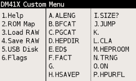
Additional CST functions
Pressing key 1 to 6 activates one of special functions:
-
Help - Activates help browser. Note that it requires "/HELP/41x.html" file on disk. The latest help file is available at http://technical.swissmicros.com/dm41x/fat/HELP/41x.html.
-
ROM Map - Invokes Module ROM Map screen
-
Load RAW - Invokes Load RAW Program
-
Save RAW - Invokes Save RAW Program
-
USB Disk - Invokes Activate USB disk
-
Flags - Shows Flags Screen
3.3.2. CONF Screen
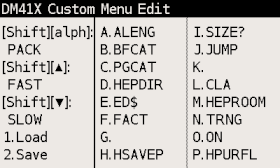
The CONF screen allows editing key assignments as well as load and save
all the assignments from/to disk.
Edit Commands
You can press A to P to start command editor for particular key or ▲, ▼ or α for special key.
Edited command is displayed with black background.
Then you can write the command. Use SHIFT to enter special characters,
-
← Deletes last character and aborts edit if edit field is empty
-
R/S Confirms the entered command
-
ON Key aborts edit immediately
Load/Save of CST assignments
-
1 key activates the screen for loading of CST assignments from the file.
-
2 key activates the screen for saving of current CST assignments to file.
Default location for load and save is
/KEYSdirectory.
3.4. Persistent Configuration Settings
Calculator’s User Configuration (UConf) settings are persistently stored in internal flash memory. Therefore all the settings are preserved over calculator RESET, firmware update or even when the battery is removed.
3.4.1. List of Configuration Items
Items marked with
-
→ [UConf] are stored in persistent backup
-
→ [.d41] are part of State files, therefore not stored in UConf
- DMY setting
-
Note that date format format setting is stored in two places as YMD is extension of 41C formats
YMD setting → [UConf]
DMY (Flag 31) → [.d41] - CLK24 setting
-
Bit 6 of scratch register B → [UConf]
- Mute flag
-
Flag 26 → [.d41]
- Display modes
-
Stack mode → [UConf]
Program mode → [UConf] - Module screens
-
Two column flag → [UConf]
Short name flag → [UConf] - System configuration
-
Slow auto repeat → [UConf]
Printer line delay → [UConf]
3.4.2. Export of Configuration Settings
Configuration Settings can be saved into the file from the menu Setup → Setings → "Export Settings to 'param.cfg'"
USB Disk Mode is automatically entered after the param.cfg file is written.
3.4.3. Restore of Configuration Settings
User can copy param.cfg file to root of the FAT disk.
The FAT disk is checked for presence of the /param.cfg file after each deactivation
of USB Disk Mode and configuration settings are restored from this file.
The /param.cfg file is removed afterwards.
3.5. Flags Screen
Shows values of all 56 flags in one screen.
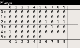
3.6. LCD Screenshots
Hold SHIFT and press DISP to get a screenshot.
You will find a .bmp file named according to the current time and date in the /SCREENS folder of the FAT drive.
3.7. OFF Images
The LCD display used in DM41X calculator behaves in similar way as e-ink displays and contents of the LCD is visible for a long time after the calculator is turned OFF.
This feature is used to display images when the calculator is turned OFF.
Single hard-coded OFF image is present in calculator firmware and this image is displayed whenever the calculator is turned OFF and FAT disk doesn’t contain any valid custom image or the FAT disk is in error state.
Custom OFF images should be stored in /OFFIMG/ directory. All valid images are then cyclically displayed one after
each calculator OFF in the order how they appear in /OFFIMG/ directory.
OFF images require specific image format. It has to be .bmp file with dimensions 400 x 240 and 1 bit depth.
Examples of OFF images can be found on "A collection of off-screen images" page.
3.8. RTC correction
Note that to apply RTC correction you have to know (measure and calculate) ppm drift of calculator clock first.
Use following steps to apply clock frequency correction.
-
Calculate correction factor C which best matches required ppm correction P
C = 2^20 P /(10^6 + P)
resulting value C has to be integer and -511 <= C <= 512.
-
Create file
/rtccalib.cfgin root directory of calculator FAT disk and write value C there. -
Once the RTC correction is active the ppm value is written in Setting menu at the end of "Set Time >" line.
It is possible to use approximate expressions between correction factor C and ppm value P (with reasonable precision):
C = 1.04858 P
P = 0.953674 C
3.9. Patched mainframe ROMs
Changes to the original NUT-CX.MOD - 30.08.2019, by Ángel M. Martin
Fitting all these into the ROMS wasn’t terribly difficult, although there were numerous restrictions both in available space and FAT sizes. The ROMS are totally full now..
3.9.1. Patch to routine [MASK]
Needed for ALPHA display of lower-case characters. The Half-nut LCD display is capable of displaying lowercase chars but the 41CX-OS code wasn’t modified to display them properly in ALPHA. This patch corrects that.
More on this here: Forum Article
3.9.2. (Minor), Changed the ROM2 revision
From "N" to "X", and the Section Header names in CAT 2 for CX-FNS and CX-TIME
3.9.3. Added SLOW and FAST functions
Intended to control the relative speed of DM41X’s operation. SLOW corresponds to original 41C speed, FAST is roughly 50 times faster. Implemented by adding [TURBO0] and [TURBO50] routines to mainframe ROM2.
Accessible as new FAST/SLOW functions in the -DM_41X section
| Running in SLOW mode does not extend battery life, it is only provided for possible compatibility issues with 3rd party modules. You should generally run in FAST mode, and this is the assumed mode for normal operation. Note that running in slow mode could also have adverse visual effects in custom ROM code where heavy LCD access is used. |
3.9.4. Extensions to the ED function (ASCII file editor)
Done to support lower case and special characters. The function has been renamed ED$ to signal the additional capabilities. Same XROM code of course.
More on this here: Forum Article
3.9.5. Additional Functions
The header function -EXT_FCN_2X is stealth for CRT?, a curtain finder tool. To execute it use XROM 25,00 or assign to any key.
One additional function at the end of the -CXX_XT_FCN section, after the X#NN functions:
- X<I>Y
-
Exchanges the contents of IND X and IND Y
One additional function in the -CXX TIME group, plus a new Section after the TIME functions are listed, labeled "-DM 41X-" containing 17 functions. Both shown below:
- TRNG
-
Time-Based (True) Random Number Generator
- -DM 41X-
-
New Section header. .
- ABSP
-
ALPHA Back Space. Deletes the rightmost char in ALPHA
- AINT
-
Appends integer value from Reg X to ALPHA (includes sign)
- ASWAP
-
Swaps ALPHA strings around the comma characters, i.e. A,B changes to B,A
- CLAC
-
Clears ALPHA after the comma character, i.e. A,B changes to A,
- CLEM
-
Clears all Extended Memory
- FAST
-
Restores FAST mode
- FILL
-
Fills the stack with the value in X
- FLCOPY
-
Copies the content of a file into another. Both files must exist and be of the same type. The destination file should be of equal size or larger than the source file.
- FLHD
-
Returns to X the address (in decimal) of the File Header. Stack lifts if CPU F11 is set
- FLTYPE
-
Returns to X the type of the file, ie. 1 for program, 2 for Data, etc… Stack lifts if CPU F11 is set
- LKAOFF
-
Turns Local KA (Key Assignments) off, i.e. those assigned to the two top rows
- LKAON
-
Turns Local KA (Key Assignments) back on
- RENMFL
-
Renames an X-Mem file. Alpha contains OLDNAME,NEWNAME
- RETPFL
-
Re-types an X-Mem file. X has the new type value (1 to 15)
- SLOW
-
Sets SLOW mode for compatibility with legacyModules
- WORKFL
-
Appends the name of the current ("Working") X-Mem file to ALPHA.
4. Modules
Integral part of original HP-41 are pluggable modules. This chapter explains how to load and manage modules in DM41X.
4.1. Quick Module Load
This is quick step by step reference how to load module.
You can use ▲, ▼ keys to navigate items.
Plug, Imprt, etc. corresponds to soft menu items and are activated by respective first-row key.
Steps
Load .mod file to DM41X
-
First you need to prepare module as
.modfile -
Copy
.modfile to calculator’s FAT disk (preferably to the/MODSdirectory)
See Activate USB disk how to copy files to calculator’s FAT disk.
Load .mod file to internal Flash Module area
-
Navigate to
SETUP → Module → Active Modules → Plug → Imprt -
Select
.modfile from the file list, press ENTER to load.
Now you should see list of modules present in Flash Module area
Add module to the "Active Modules" list
-
Select your module and press Add key from soft menu. You should see
Active Modulesscreen -
Press ENTER to accept
Active Moduleslist.
Now the module should be active.
4.2. Printer Modules
The "Thermal Printer" module is pre-loaded in the calculator’s flash memory, ready to make active.
The "IR Printer" module (available at http://www.hp41.org/LibView.cfm?Command=View&ItemID=449)
must first be copied to the calculator’s FAT storage in the \MODULES folder,
and then imported into Manage Modules in Flash,
prior to plugging-in the modules as detailed below.
Here is a quick step-by-step reference for how to activate a printer module:
Steps
-
Navigate to
SETUP → Module →Active Modules. -
Press Plug.
-
Select
Thermal PrinterorIR Printerand press Add or ENTER. The module you selected should be in theActive Moduleslist now. -
Press ENTER to accept new
Active Moduleslist.
4.3. Supported Module formats
DM41X is able to load and use usual .mod files only.
However you can always pack ROM file(s) into .mod on PC and use resulting .mod file at DM41X.
4.4. Flash Module Area
"Flash Module Area" is special region of flash memory dedicated for module use. It is the only place from where the emulator can access module ROMs and run module code.
That implies all modules before activation have to be loaded to "Flash Module Area".
Tools for module management in "Flash Module Area" are accessible from screen
SETUP → Module → Manage Modules in Flash.
4.4.1. Module identification in flash
Flash Module Area can only be populated by loading module files from FAT disk. Original path of each
loaded .mod file is stored by load process in flash along the module data.
| You can check the module filename in flash by going to Setup → Module → Manage Modules in Flash, then select appropriate module and use Mod to display module info. |
A module is considered to be loaded in flash if its filename (i.e. without directory) is the same using case insensitive comparison.
4.5. Backup Module Lists
This functionality allows to save and load list of modules stored in
Active Modules (AM) list.
Also allows to save list of currently loaded modules in flash module area.
Further, contents of flash module area can be restored based on the saved module list
(which requires corresponding .mod files to be present on FAT disk).
Module lists are saved into .m41 files, default load/save directory is /STATE.
The .m41 file contains only list of module filenames and flags whether the particular module
is active (i.e. comes to both AM list and flash module area)
or is non-active and should be stored into flash module area only.
|
Setup → Module → Save Modules
-
Save Active Modules (AM) List only
Saves list of modules present in current AM list (all modules are marked as active in saved file). -
Save Flash and AM Lists
Saves list of modules present in current AM List (marked as active in saved file) followed by list of remaining non-active modules in flash area (marked as inactive in saved file).
Setup → Module → Load Modules
-
Load Active Modules (AM) List
Fills AM List with active modules from given file.
All modules have to be already present in flash. See Module identification in flash for more details. -
Load Flash and AM List
Clears module flash area and AM list.
Then loads all modules from given file into flash and fills AM list with active modules. -
Load Flash, clear AM List
Clears module flash area and AM list.
Then loads all modules from given file into flash and leaves AM list empty.
4.6. Activating Modules (plug-in)
Here "Activating module" means to do an action which corresponds to module plug-in on real calculator.
Note that it is possible to plug-in only modules present in Flash Module Area.
Steps
-
Activate Plug from "Active Modules" screen:
SETUP → Module → Active Modules → Plug -
List of modules from Flash Module Area is displayed

-
If required module isn’t present in the list you can import module from disk using Imprt now.
-
Select required module from list and press Add or ENTER to add module to "Active Modules" list.
You should seeActive Modulesscreen now. -
Press ENTER to accept
Active Moduleslist.
Now the module should be active.
4.6.1. Troubleshooting
Actual layout of loaded modules could be seen in ROM Map screen.
4.7. Internals
4.7.1. Module Loader
This section describes procedure for ROM address assignment.
Each time module is plugged or unplugged Module Loader assigns locations of ROMs to active modules.
For each step number below are all active modules processed in order specified in Active Modules screen:
- Pass 0
-
ROMs assigned in
.modfiles to fixed pages go exactly there. - Pass 1
-
Others ROMs are assigned to pages 8-F in order of appearance - first those with prescribed mutual relative positions (in single
.modfile). - Pass 2
-
Finally ROMs using single pages with no other requirements are placed at free pages.
Note that in above-mentioned steps ROM refers to item in .mod file which can actually
represent also RAM page.
|
4.7.2. RAM pages
Any module can define its own RAM (in .mod file) and subsequently access it using WROM(WMLDL) and CXISA(FETCH S&X).
HEPAX instructions WPTOG and BLKMOV are implemented too.
If you are going to use RAM pages in multiple modules or you want to change modules which uses RAM pages:
| The contents of RAM pages are internally linked to the order of RAM pages requested during module load. That means these contents are strictly tied to a particular configuration of modules containing RAM pages. We recommend you make RAM backup (or full backup) whenever you change configuration of RAM modules unless you really understand the consequences. |
RAM pages are initialized when the module is used (plugged-in) for the first time after loading Flash from FAT; RAM page contents are loaded with data from the appropriate RAM page of the .mod file. In most cases this means the RAM is cleared, however this allows the user to create a module with pre-filled RAM contents. Otherwise the contents is preserved during all plug/unplug(s) of modules. Note that changes to these RAM pages are not saved to the .mod file, however you can save the complete RAM contents as described here and in the Save RAM Pages section.
System offers 8 RAM pages organized as ordered list called RAM Area.
RAM pages from this area are linked to modules by
Module Loader in order as they are requested by modules.
Thus RAM pages are assigned in the same way for the same module configuration preserving the
correct RAM contents for modules.
As a consequence moving modules containing RAM pages doesn’t harm their RAM contents as far as all modules with RAM preserve the same order in Active Modules list and module itself is able to handle RAM page changes.
It is possible to load and save contents of RAM Area using
Load RAM Pages and Save RAM Pages commands.
Load RAM Pages loads all pages from the file to the beginning of
the RAM Area. Thus contents of RAM pages can be loaded before activating module
which will use those pages.
Note that when loading a saved file that has more pages than are currently allocated, the additional pages will still be loaded into the following unallocated space. Thus, if/when allocated to another module in the future, these pages will contain the same contents as when loaded. If intended for other use, you may need to clear those pages before use.
Save RAM Pages saves currently used pages from RAM Area.
4.7.3. Extended Memory
Memory summary (in registers)
| DM41L | DM41X | |
|---|---|---|
Main memory |
319 |
319 |
Extended memory |
362 |
600 |
Main memory contains 319 registers initially configured for 100 data registers and 219 registers for programs and other data (alarms, key definitions, etc). This split between data registers and program can be changed by SIZE command. Extended memory is used to store programs, data, and text files. Program or data has to be copied to main memory so it can be run or accessed from program. Base extended memory is 124 registers, and each extended module adds 238 to it. Thus, you can get 362 extended memory registers with a single extended module (DM41L) or 600 registers with two extended modules (DM41X).
5. Program Decoder/Encoder
There is state file decoder/encoder available at http://technical.swissmicros.com/decoders/dm41/.
Besides loading of contents of state files (which has to be copied into "Dump from calc:" window).
It also allows to load .raw program files.
For more details follow the encoder link and look into "Quick Ref" tab.
| (To be implemented…) Note that this utility is originally designed for DM41 and needs update to fully support all features of DM41X. |
6. DM41X Menus
- Menu navigation
-
-
Select menu items using ▲, ▼ keys.
-
Activate current menu item by pressing ENTER key or by pressing the number key corresponding to particular menu line.
-
Return to previous menu level by ON or ← key.
-
- Soft menus
-
-
Sometimes soft menu like this is displayed at the bottom of the LCD:

Each item in soft menu corresponds to respective key in first-row and pressing corresponding key activates particular item.
-
- Navigation in lists
-
File lists, Module list and Active Modules list
-
EEX key switches between 1-column and 2-column mode
-
CHS key skips between the left and right columns
-
- "EXIT" key
-
-
As the DM41X is based on more general DMCP system, there could be occasional references to the "EXIT" key which means to press the ← on DM41X.
-
6.1. Main Setup menu
Main "Setup menu" could be entered by pressing SHIFT+SETUP.
From there other sub-menus could be entered or about screen displayed
-
About > Displays About screen.
6.2. File menu
6.2.1. Load DM41 State File >
Used for loading the .d41 state files. By default from the /STATE/ directory of the FAT disk.
Note that this loads only calculator memory and doesn’t affect state of currently loaded modules.
To load calculator state
-
Select the program to load using the ▲ and ▼ keys
-
ENTER to load the selected state file
-
Warning is displayed that current calculator state will be lost. Proceed with ENTER.
Then calculator state is updated from the selected file.
6.2.2. Save DM41 State File >
Used for saving calculator’s state (i.e. contents of memory and CPU registers) to a .d41 state file. By default to the /STATE/ directory of the FAT disk.
-
Select file from list (for overwrite) or
<New File>if you want to enter new filename.
Confirm with ENTER -
[On
<New File>] Enter new filename. SHIFT toggles input mode between lower/upper case and numbers.
Confirm with R/S or Alpha.
Then calculator state is saved to selected file.
6.2.3. Load RAW Program >
Used for loading the .raw program file from FAT disk. By default from the /PROG/ directory of the FAT disk.
This is functional equivalent of GETP extended memory command. Only this reads from FAT disk instead of extended memory.
To load program file:
-
Select the program to load using the ▲ and ▼ keys
-
ENTER to load the selected program file
The program is loaded into calculator memory.
6.2.4. Save RAW Program >
Used for saving program to a .raw file to FAT disk. By default to the /PROG/ directory of the FAT disk.
This is functional equivalent of SAVEP extended memory command. Only this writes to FAT disk instead of extended memory.
-
Put the name of the program (the topmost global label) you want to save in Alpha.
Note that you can save the current program (the one you are actively in, seen in line 3 of SI mode) by ensuring that Alpha is clear.
Also note that for filenames, a key difference is that in a CX, the program name can use any 41 characters to make up the filename, whereas when exporting to USB storage, you must use only "normal" characters for the filename. So you can’t specify 41-unique characters in the filename such as "%", "↑", "Σ", etc.
-
Select file from list (for overwrite) or
<New File>if you want to enter new filename.
Confirm with ENTER -
[On
<New File>] Enter new filename. SHIFT toggles input mode between lower/upper case and numbers.
Confirm with R/S or Alpha.
The program is saved from calculator memory to FAT disk.
6.2.5. Activate USB Disk
Used to copy files from/to a host computer - e.g. backup/restore the calculator state files from /STATE/ directory or read/write programs in RAW format into the /PROG/ directory.
-
Connect the calculator to a computer using a USB cable
-
The DM41X’s flash disk should be visible on the computer
-
Read/write files
-
"Eject device" on the host machine.
-
Calculator should end USB disk mode automatically if correctly ejected by OS.
You can also end USB disk mode by pressing ← or ON key on the calculator followed by ENTER key for confirmation, but be sure all data are flushed to disk first.
| The last two points "Eject device" and eventually "Press ← or ON key on calculator" if USB disk mode doesn’t end automatically are important to avoid unsaved data and possible FAT disk corruption! |
For Windows users
In Windows you can eject the disk in two different ways:
-
(Prefered) Right-Click on the drive in any Explorer view and select "Eject" and the DM41X should leave USB Disk mode automatically.
-
Click the "Safely remove hardware and eject media" icon in the tray, then select DM41X from the list of devices to eject. After you see the "Safe to remove hardware message" press ← or ON key followed by ENTER key for confirmation to exit USB Disk mode.
6.2.6. Show Disk Info
Displays disk status and disk block info.
6.3. Module menu
6.3.1. Active Modules (AM)
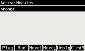
You can use x<>y or DSP key to switch the module labels between
Title from .mod file and module filename (without directory and extension).
|
Soft menu items:
- Plug - Plug-in module
-
Add module to active modules list. See Activating Modules section.
- Mod - Module Info
-
Displays information about selected module.
- Move↑ - Move up
-
Move selected module in list up.
- Move↓ - Move down
-
Move selected module in list down.
- Unplg - Unplug module
-
Deactivates module by removing from active modules list.
- ClrAM
-
Clears active modules list.
6.3.2. Manage Modules in Flash
Note that "Flash" refers here to "Flash Module Area".
"Manage Modules in Flash Screen" allows to add/remove modules to/from this area as well as display various information about modules and flash module area state.
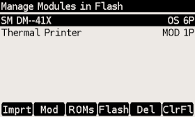
You can use x<>y or DSP key to switch the module labels between
Title from .mod file and module filename (without directory and extension).
|
Soft menu items:
- Imprt - Import Module
-
Opens file selection dialog in
/MODSdirectory (which is default directory for.modfiles).
Select module file and press ENTER to import it into "Flash Module Area". - Mod - Module Info
-
Displays information about selected module.
- ROMs- Module Page Info
-
Technical information about page assignment of currently loaded modules. Note that the XROM ID for each page, if present, is shown in parenthesis after the page header info.
- Flash - Module Memory (Flash Area) Info
-
Information about whole "Module Flash Area".
- Del - Delete Module
-
Removes module from flash.
- ClrFl
-
Clears active modules list and all modules from
Module Flash Area.
6.3.3. Module ROM Map
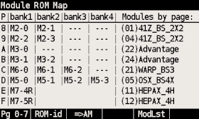
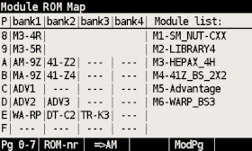
ROM map shows ROM placement in pages and banks.
Each row corresponds to page denoted at the beginning of the line, columns
represent banks.
RAM pages are shown in first bank if other only as RAM banking isn’t supported now.
Module ROM Map screen consist of two parts:
-
Actual ROM map at the left
-
Module list at the right
Module list has two options:
-
"Module list" lists all modules by module IDs, which are used in ROM labels. Left and right side are independent and only linked by module IDs.
-
"Modules by page" displays module names corresponding to ROM/RAM for particular page in bank1. Note that the XROM ID for each page, if present, is shown in parenthesis just in front of the module name.
Soft menu items:
- Pg 8-F/Pg 0-7 - Toggle page range
-
Toggles view between page ranges 0-7 and 8-F.
- ROM-id/ROM-nr - Toggle ROM labels
-
-
ROM-id ROM id from
.modfile -
ROM-nr ROM label in the form of "<module_id>-<rom_nr>", where
-
<module_id> is module id according to the right column
-
<rom_nr> is ROM sequence number from
.modfile (counted from 0)
-
-
- ⇒ AM
-
Invokes Active Modules screen.
- ModLst
-
Switches right side between "Modules list" and "Modules by page"
6.3.4. Load Modules
Activates Load Modules sub-menu:
-
Load Active Modules (AM) List
-
Load Flash and AM Lists
-
Load Flash, clear AM List
See Backup Module Lists for details.
6.3.5. Save Modules
Activates Save Modules sub-menu:
-
Save Active Modules (AM) List only
-
Save Flash and AM Lists
See Backup Module Lists for details.
6.3.6. Load RAM Pages >
Fills RAM Area from the file.
6.4. Settings menu
6.4.1. Set Time >
Used for setting the time.
-
Use the function keys to adjust the time.
-
Press Set to write the new time to the calculator clock or ← to cancel your changes.
6.4.2. Set Date >
Used for setting the date.
-
Use the function keys to adjust the date.
-
Press Set to write the new date to the calculator clock or ← to cancel your changes.
-
Σ+ could be used to change between DMY/MDY formats.
6.4.3. Slow Auto-repeat
Selecting this menu item toggles the "Slow Auto-repeat" flag.
When the "Slow Auto-repeat" flag is active auto-repeat delays are prolonged.
Note that this value is stored in persistent configuration.
6.4.4. Printer Line Delay
This parameter sets printer line delay and is essential when using the "Thermal Printer" module since it doesn’t recognize the DELAY command.
It specifies how long the calculator waits between sending lines of information to the HP 82240A/B Thermal Printer.
The value is the delay time, in seconds. Default value is 1.8s.
Note that fastest line printing time for HP 82240A/B is approx. 1s, lower values of printer line delay are intended for IR printer emulators.
The value is stored in persistent configuration.
| When using the "IR Printer" module, the delay time reported in the Settings menu may differ slightly from the value set using the DELAY command due to internal processing. |
6.4.5. Create Full Backup
Creates five files in /BACKUP directory:
-
.b41 - Base backup file
-
.cst - CST keys
-
.d41 - State file
-
.m41 - Module lists
-
.ram - RAM pages
All those files use the same name and different extensions. Core backup file
has extension .b41 and contains list of all files related to the particular
backup.
6.4.6. Restore from Backup
User selects a .b41 file and all referenced files are automatically loaded.
All the referenced files have to be in the same directory as the .b41 file.
For "distribution" purposes (e.g. when shared between users) unused files could
be removed (both the file and reference in .b41 file).
During restore the .mod files are primarily looked up in .b41 directory when
loaded from .m41 file.
6.4.7. Export Settings to "param.cfg"
Writes configuration settings (UConf) to the /param.cfg file.
See Persistent Configuration Settings for more details.
6.4.8. Reset settings to defaults
Resets Persistent Configuration Settings to defaults.
6.5. System menu
6.5.1. Flash firmware from FAT
Starts flashing of new firmware if the firmware file is stored in root directory of FAT disk. This is usually not necessary because calculator automatically detects presence of new firmware file and asks for update after end of USB disk mode.
See Firmware update chapter for more information about firmware update.
6.5.2. Bootloader
Activates bootloader mode for firmware flashing.
You can flash DM41X firmware once is the bootloader mode entered. See Firmware update chapter for more information about firmware update.
Press the RESET button on the back of the calculator if you activate Bootloader mode accidentally.
6.5.3. Program Info
Displays information about currently loaded DM41X. This is mainly for diagnostics.
6.5.4. Reset to DMCP menu
Reboots calculator back to DMCP system menu.
| All unsaved data is lost. Save your DM41X state before proceeding to the DMCP menu, see Save DM41 State File. |
6.5.5. Format FAT Disk >
Format the internal FAT disk storage.
| All data is erased from disk. |
After formatting the FAT disk, all default folders described in section Internal FAT disk will be automatically created.
6.5.6. FAT Disk Media Test >
Checks whole flash disk FAT area for bad blocks. Disk is formatted starting from first good block after the check.
| All data is erased from disk. |
6.5.7. Power OFF mode
This item is purely for power OFF testing purposes to avoid time consuming switching between firmwares. It is in no way mentioned to be changed by users.
-
Mode 0 means no deep sleep for QSPI giving approx. 12uA sleep current.
-
Mode 1 corresponds to pre 3.9 DMCP behavior.
-
Mode 2 corresponds to DMCP 3.9 and newer versions.
-
Mode 3 is the latest update to mode 2 which should fix possible deficiencies of mode 2 by adding further pull-ups.
Defaults:
hwid=0 : Mode 1
hwid=1 : Mode 3
Note that the "Power OFF mode" value is preserved during calculator RESET, but is lost when battery is removed.
6.5.8. Self Test
Displays production test menu where tests of various parts of calculator could be run from.
Self Test menu
1. KBD Test
2. LCD Test
3. IR Test
4. BEEP Test
5. Diagnostics
7. Firmware Update
| Please remember it is always wise to make FAT disk backups periodically and especially before any update. |
For quick update instructions, please follow Quick Update Guide.
The preferred firmware update method is by copying firmware file to calculator FAT disk. See Quick Update Guide for update procedure.
Firmware update from FAT disk is implemented in main firmware, so it could be unavailable if the main firmware is corrupted. In such a case, another method of update based on internal CPU flashing routine should be used. This method requires the calculator to be switched in so called 'Bootloader mode'. Once activated, the internal bootloader exposes standard DFU interface and can be programmed by any DFU programming software.
Following sections cover the use of two programs able to use this DFU interface:
Availability of the particular update method on mainstream operating systems outlines following table:
| FAT disk[1] | dm_tool | dfu-util[2] | |
|---|---|---|---|
Windows |
✓ |
✓ |
✓ |
Linux i686 |
✓ |
✓ |
✓ |
Linux x86_64 |
✓ |
✓ |
✓ |
macOS |
✓ |
✓ |
[1] FAT disk update was made available starting with DMCP version 3.5; therefore, a calculator with an earlier firmware version must be updated with one of the other methods.
[2] macOS users can get dfu-util via Homebrew.
7.1. Quick Update Guide (FAT disk update)
This chapter describes update of complete DM41X firmware (i.e. DMCP system, DM41X program and flash area) at once using combined firmware file.
- Prerequisites
-
DMCP_flash_x.x_DM41X-y.y.bin- Complete DM41X firmware file e.g.DMCP_flash_3.16_DM41X-1.10.bin
Steps
-
Activate USB disk from
SETUP → File → Activate USB Diskor alternatively from DMCP System menu. -
Connect USB cable from DM41X to PC/Mac computer.
-
Copy the
DMCP_flash_x.x_DM41X-y.y.binfile from the PC/Mac computer to root folder of calculator disk. -
Eject (safely remove) the calculator disk from PC/Mac computer. Please, be patient this can take some time. Do not unplug the cable, even after the calculator’s USB disk has been successfully ejected by the OS, as USB power is required for the rest of the procedure.
-
If calculator does not detect OS ejection, shut down USB connection by pressing C. New firmware file is detected and the calculator prompts for update. Confirm it immediately with ENTER or cancel by pressing EXIT to activate flashing process later using
Flash firmware from FATeither from DM41X programSETUP → Systemor directly from DMCP System menuEnter System Menu. -
Flash progress is displayed from 0 to 100%. An automatic verification pass follows.
-
Once finished, the calculator resets and should restart to updated DM41X.
| Any State which hasn’t been saved to a Statefile prior to updating is lost. |
7.2. Bootloader mode activation
Bootloader mode can be activated from main Setup menu: SETUP → System → Bootloader
or by using RESET and PGM button.
The sequence of entering bootloader mode using RESET and PGM button is:
-
Press and hold PGM button
-
Press and release the RESET button
-
Release the PGM button
Older models have both buttons accessible through the holes in the calculator backplate.
Newer models have one hole in the backplate for RESET button only, therefore the backplate should be removed first, then use the RESET and PGM buttons directly on PCB.
7.3. FW Update Using dm_tool
The latest version of dm_tool can be downloaded from
the Tools web page.
|
7.3.1. Prerequisites for Windows
Install libusb driver as described here: http://technical.swissmicros.com/doc/libusb_install/libusb_install.html.
7.3.2. Prerequisites for Linux
USB device access rights: this configuration is optional.
Allow access to the DFU device for users in plugdev group by running as root:
cd /etc/udev/rules.d/
cat << OI > 49-stm32-dfuse.rules
# This is udev rules file (place in /etc/udev/rules.d)
# Makes STM32 DfuSe device accessible to the "plugdev" group

ACTION=="add", SUBSYSTEM=="usb", ATTRS{idVendor}=="0483", ATTRS{idProduct}=="df11", MODE="664", GROUP="plugdev"
OI
udevadm control --reload-rules
Then add users to plugdev group.
7.3.3. Launching dm_tool
- Switch the calculator to bootloader mode
-
From menu or by RESET+PGM buttons (see Bootloader mode activation).
- Connect the calculator to the PC
-
Be sure the libusb driver is installed if used in Windows (http://technical.swissmicros.com/doc/libusb_install/libusb_install.html).
- Launch
dm_tool -
It can be launched by clicking on the exe file or from command line with firmware filename as argument.
If everything works well and the calculator was connected before launching dm_tool,
then the message on the right side of [Program] button should show device number.
If it shows "No DFU capable devices found (Click to refresh)" try to click at the message
and it should display the ID of connected device after refresh and
Memory layout:
    0x8000000-0x80fffff:  size 1024kB = 512*2kB pages
in the text area.
If the message "No DFU capable devices found" still remains there something is wrong with libusb driver installation or connection to the calculator or the calculator isn’t in bootloader mode.
Finally press the [Program] button to flash new firmware.
When the update is completed, you can close dm_tool, then Press [ON] to launch the new f/w.
7.4. FW Update Using dfu-util
| macOS users can get dfu-util via Homebrew |
Linux users (and possibly macOS users too) can avoid sudo use by setting appropriate user rights
for DFU interface, see user rights configuration for Linux.
|
Note that dfu-util is command line utility launched from a terminal application and controlled by commands from the console.
For new users, here are some tutorials on how to use command-line interfaces:
Proceed with the following steps:
- Switch the calculator to bootloader mode
-
From menu or by RESET+PGM buttons (see Bootloader mode activation).
- Connect the calculator to the computer
-
List information about connected DFU device using console command
sudo dfu-util -lSample output of this command (from macOS)
$ sudo dfu-util -l
Password:
dfu-util 0.9

Copyright 2005-2009 Weston Schmidt, Harald Welte and OpenMoko Inc.
Copyright 2010-2016 Tormod Volden and Stefan Schmidt
This program is Free Software and has ABSOLUTELY NO WARRANTY
Please report bugs to http://sourceforge.net/p/dfu-util/tickets/

Deducing device DFU version from functional descriptor length
Found Runtime: [05ac:828b] ver=0149, devnum=6, cfg=1, intf=3, path="29-1.8.1.3", alt=0, name="UNKNOWN", serial="UNKNOWN"
Found DFU: [0483:df11] ver=2200, devnum=14, cfg=1, intf=0, path="20-4", alt=2, name="@OTP Memory /0x1FFF7000/01*0001Ke", serial="207B35994E34"
Found DFU: [0483:df11] ver=2200, devnum=14, cfg=1, intf=0, path="20-4", alt=1, name="@Option Bytes  /0x1FFF7800/01*040 e/0x1FFFF800/01*040 e", serial="207B35994E34"
Found DFU: [0483:df11] ver=2200, devnum=14, cfg=1, intf=0, path="20-4", alt=0, name="@Internal Flash  /0x08000000/512*0002Kg", serial="207B35994E34"
Where lines
Found DFU: [0483:df11]indicate that calculator is correctly connected to the computer and switched into bootloader mode. - Prepare firmware file
-
Download the latest firmware file from https://technical.swissmicros.com/dm41x/firmware/ and ensure it is accessible from current directory in console e.g. by
ls -l DMCP_flash_3.16_DM41X-1.10.bin.Alternatively, download firmware file directly to current directory using command (edit to use correct firmware file name according to before-mentioned page)
curl -O https://technical.swissmicros.com/dm41x/firmware/DMCP_flash_3.16_DM41X-1.10.bin - Launch dfu-util command
-
Start flashing using command (edit to use correct firmware file name)
sudo dfu-util -D DMCP_flash_3.16_DM41X-1.10.bin -d 0483:df11 -a "@Internal Flash /0x08000000/512*0002Kg" -s 0x8000000Please, be patient, as the operation takes some time (up to a few minutes).
Press RESET button after
dfu-utilfinishes the flashing.
Example output of dfu-util
$ dfu-util -D DMCP_flash_3.16_DM41X-1.10.bin -d 0483:df11 -a "@Internal Flash  /0x08000000/512*0002Kg" -s 0x8000000
dfu-util 0.9

Copyright 2005-2009 Weston Schmidt, Harald Welte and OpenMoko Inc.
Copyright 2010-2016 Tormod Volden and Stefan Schmidt
This program is Free Software and has ABSOLUTELY NO WARRANTY
Please report bugs to http://sourceforge.net/p/dfu-util/tickets/

dfu-util: Invalid DFU suffix signature
dfu-util: A valid DFU suffix will be required in a future dfu-util release!!!
Opening DFU capable USB device...
ID 0483:df11
Run-time device DFU version 011a
Claiming USB DFU Interface...
Setting Alternate Setting # 0 ...
Determining device status: state = dfuERROR, status = 10
dfuERROR, clearing status
Determining device status: state = dfuIDLE, status = 0
dfuIDLE, continuing
DFU mode device DFU version 011a
Device returned transfer size 2048
DfuSe interface name: "Internal Flash  "
Downloading to address = 0x08000000, size = 756288
Download	[=========================] 100%       756288 bytes
Download done.
File downloaded successfully

real	1m55.929s
user	0m0.044s
sys	0m0.048s
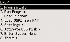
7.5. DMCP System Menu
This is main menu of DMCP system (i.e. operating system of the calculator).
This menu is automatically displayed if DMCP system doesn’t contain any loaded program or starting of the program fails.
If there is valid program loaded into DMCP system it is automatically started after RESET and thus the DMCP menu isn’t displayed.
To force DMCP menu start you can use F1+[RESET] (i.e. upper left key + RESET button through the hole in calculator backplate).
7.5.1. Program Info
Displays information about program loaded into DMCP system.
7.5.2. Run Program
Starts currently loaded program.
7.5.3. Load Program
Displays selection dialog to choose among programs stored in FAT root directory. Loads selected program to DMCP system.
7.5.4. Load QSPI from FAT
Starts flashing of the QSPI firmware. The firmware DM41X_qspi_xxx.bin or DMCP_qspi_xxx.bin
is expected to be stored in the FAT filesystem root directory.
Note that some programs dont use QSPI firmware area (e.g. the DM41X).
If Program Info displays QSPI NOT USED then the contents
of the QSPI firmware area is irrelevant for proper run of the program.
|
7.5.6. Activate USB Disk
Used to copy files from/to a host computer.
-
Connect the calculator to a computer using a USB cable
-
The DM41X’s flash disk should be visible on the computer
-
Read/write files
-
'Eject device' on the host machine.
-
Calculator should end USB disk mode automatically if correctly ejected by OS. You can end USB disk mode by pressing EXIT key on the calculator but be sure all data are flushed to disk first.
| The last two points 'Eject device' and 'Press EXIT key on calculator' (if it doesn’t end automatically) are important to avoid unsaved data and possible FAT disk corruption! |
7.5.7. Enter System Menu
Jumps to the main System menu
7.5.8. About
Displays general information about DMCP system

8. Calculator troubleshooting
| Symptom | Possible cause | Fix |
|---|---|---|
Calculator doesn’t power on, or is unresponsive after power on. |
Unsupported module, invalid module combination or other module error throws calculator in an infinite loop. |
Reflash the calculator firmware. This clears the Flash Module Area and breaks the loop. Here is how:
|
Repeated Exception/Hard Fault screen. |
Low battery (even if battery indicator shows full; indicator isn’t always showing correct information; very flat CR2032 batteries discharge curve makes low voltage condition difficult to measure accurately). |
Replace battery; use fresh battery from a reputable brand. |